
Method for preparing electrowetting display support plate

An electrowetting display and support plate technology, applied in optical components, optics, instruments, etc., can solve the problems of difficulty in controlling the dissolution rate and flatness, and can not fully solve the problem of reflow, and achieve the effect of solving the problem of reflow.

Active Publication Date: 2014-10-08
SOUTH CHINA NORMAL UNIVERSITY +2
View PDF7 Cites 15 Cited by
  • Summary
  • Abstract
  • Description
  • Claims
  • Application Information

AI Technical Summary

Problems solved by technology

Known processing steps of heat treating the hydrophobic layer to restore its hydrophobicity do not adequately address this reflow problem
However, the method of dissolving the surface of the hydrophobic layer also has the problem of being difficult to control the dissolution rate and smoothness.

Method used


Image

  • Method for preparing electrowetting display support plate
  • Method for preparing electrowetting display support plate
  • Method for preparing electrowetting display support plate

Examples


Embodiment Construction

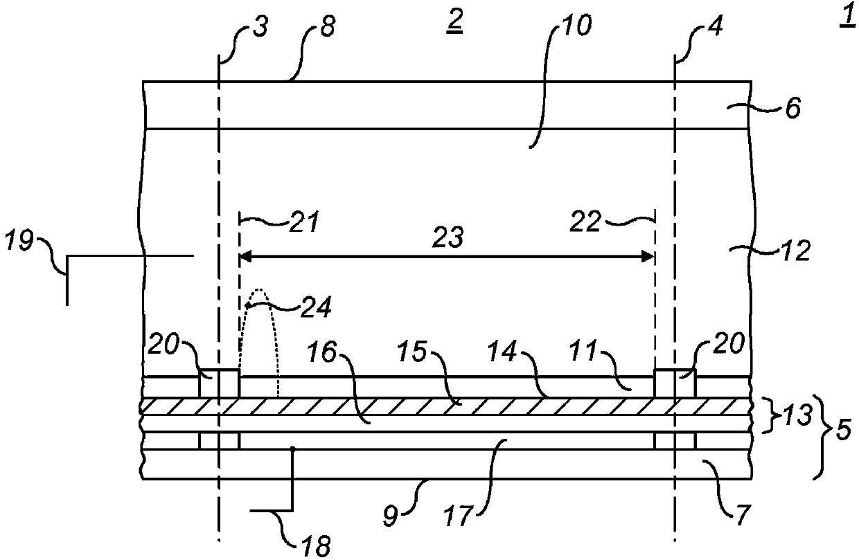
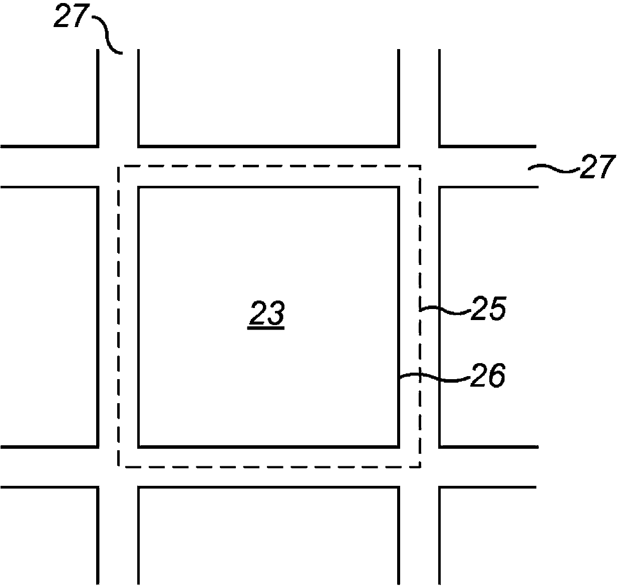
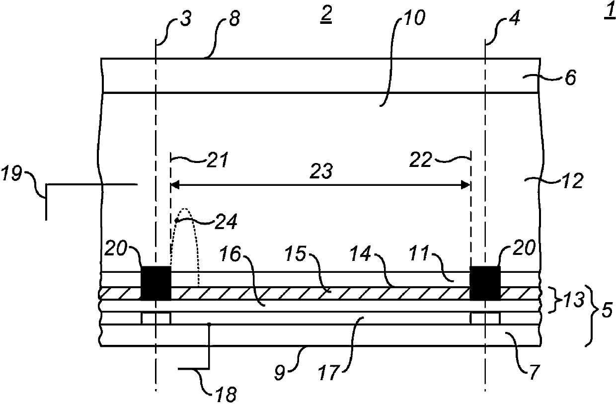
[0030] Figure 1a It is a side view of a pixel structure based on the existing electrowetting display technology, Figure 1c It is a side view of the pixel structure according to a specific embodiment of the present invention. According to the method of the present invention, an electrowetting display structure similar to that of the prior art can be manufactured. One of the most important improvements compared with the prior art is: Such as Figure 1c As shown, the pixel wall 20 is disposed on the first support plate 5 , more specifically, disposed on the dielectric layer 16 or the first electrode 17 instead of the hydrophobic layer 15 . Figure 1b Shown is a top view of the pixel structure.

[0031] Refer to the following Figure 1a-1c , to describe in detail the electrowetting pixel structure according to the present invention, wherein the pixel structure is the basis of constituting an electrowetting pixel unit. refer to Figure 1c , as an exemplary embodiment accordin...


PUM

PropertyMeasurementUnit
heightaaaaaaaaaa
thicknessaaaaaaaaaa
heightaaaaaaaaaa

Abstract

The invention discloses a method for preparing an electrowetting display support plate. The method includes the following steps: arranging pixel walls on the support plate, wherein the pixel walls are made of a hydrophilic material; applying a hydrophobic material layer on the support plate and the pixel walls; arranging at least one layer of protective layer on the hydrophobic material layer which flows into a groove surrounded by the pixel walls and covers completely the hydrophobic layer part in the groove when at a liquid state; removing the hydrophobic layer on the pixel walls through an etching process or a photoetching process; and cleaning the protective layer. The invention also discloses the electrowetting display support plate which is manufactured through the method. According to the method, the surface layer of the hydrophobic layer completely does not need processing for reducing hydrophobicity and is not subjected to damage by dissolution and a solution which cleans a barricade layer does not cause damages on the hydrophobic layer so that optimal hydrophobicity and smoothness of the surface of the hydrophobic layer are completely reserved. A backflow problem can be well solved.

Description

technical field [0001] The invention relates to a method for preparing a display support plate, in particular to a method for preparing an electrowetting display support plate. Background technique [0002] An electrowetting display device such as that described in International Patent Application WO2003 / 071346 comprises two support plates. On one of the support plates there is arranged a wall pattern (pixel wall) which defines the picture elements of the display device. The area between the walls of the picture elements (which can be pixels or sub-pixels) is called the display area, on which the display effect occurs. Areas of the support plate in the pixel display region of an electrowetting display device must be hydrophobic to a large extent for proper operation of the picture elements. During manufacture, the area of ​​the support plate in which the picture elements are located is covered by a hydrophobic layer, while the walls of the picture elements are made of a hy...

Claims


Application Information

Patent Timeline
Patent Type & Authority Applications(China)
IPC IPC(8): G02B26/00
Inventor 周国富吴昊罗伯特·安德鲁·海耶斯李发宏
Owner SOUTH CHINA NORMAL UNIVERSITY
Learn More