
A low loss rectifier circuit

A rectifier circuit and comparison circuit technology, applied in electrical components, AC power input into DC power output, output power conversion devices, etc., to achieve the effect of low loss, low rectification voltage drop, and reduced loss

Active Publication Date: 2016-09-07
STATE GRID CORP OF CHINA +2
View PDF7 Cites 0 Cited by
  • Summary
  • Abstract
  • Description
  • Claims
  • Application Information

AI Technical Summary

Problems solved by technology

[0007] For rectification circuits in the field of energy conversion, the lower the rectification loss, the better, so there is still room for improvement in the rectification circuits disclosed in the above patent documents

Method used


Image

  • A low loss rectifier circuit
  • A low loss rectifier circuit

Examples


Embodiment Construction

[0031] The low-loss rectifying circuit of the present invention will be further explained and described below in conjunction with the accompanying drawings and specific embodiments.

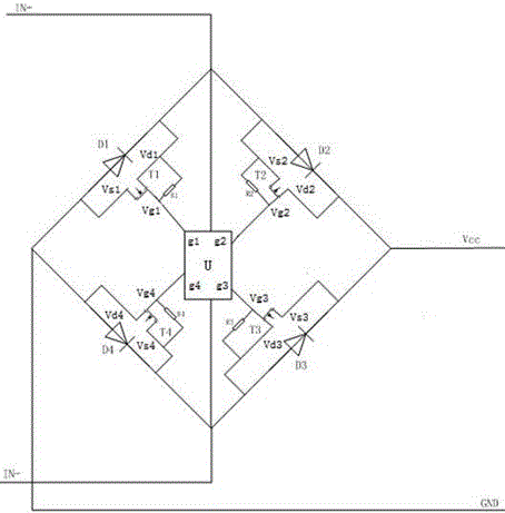
[0032] figure 1 The circuit of the low-loss rectification circuit in an embodiment of the present invention is illustrated.

[0033] Such asfigure 1 As shown, the low-loss rectification circuit of this embodiment includes: four diodes, respectively the first diode D1, the second diode D2, the third diode D3 and the fourth diode D4; The MOSFETs are respectively a first MOSFET T1, a second MOSFET T2, a third MOSFET T3 and a fourth MOSFET T4; four resistors R1, R2, R3 and R4. The connection relationship is shown in the figure, diodes D1, D2, D3 and D4 form a conventional rectifier circuit; IN+ and IN- are AC input signals, Vcc and GND are DC output signals; P-channel MOSFETs T2 and T3 are respectively connected to diode D2 Connected in parallel with D3, N-channel MOSFETs T1 and T4 are connected in...


PUM


Abstract

The invention discloses a low-loss rectifying circuit. The low-loss rectifying circuit comprises a first diode, a second diode, a third diode and a fourth diode and further comprises four MOSFETs correspondingly connected with the four diodes in parallel, and a logic control module. The logic control module comprises a signal voltage divider, a comparison circuit, an inverter and a three-state gate. The logic control module controls connection and disconnection of the MOSFETs to enable the MOSFETs to replace the diodes correspondingly connected with the MOSFETs in parallel to serve as a channel for a rectification exchange signal under the connection state. According to the low-loss rectifying circuit, the rectifying circuit has extremely low rectification voltage drop, and the loss of the rectifying circuit can be effectively reduced.

Description

technical field [0001] The invention relates to a power component circuit, in particular to a rectifying circuit. Background technique [0002] As a power component circuit, the rectifier circuit includes a bridge formed by four diodes to realize the conversion of the input AC signal to the output DC signal. [0003] In each working cycle of the rectifier circuit, only two diodes work at the same time, and through the unidirectional conduction function of the diodes, the AC signal is converted into a unidirectional DC pulsating signal. Due to the voltage drop of the diode itself, certain losses will inevitably occur in the rectifier circuit during use, especially in the field of energy conversion and acquisition, and the above losses will affect the performance of the entire circuit. Therefore, reducing the loss of the rectifier circuit is a hotspot in the field of energy harvesting. [0004] The publication number is CN102468741A, and the publication date is May 23, 2012....

Claims


Application Information

Patent Timeline
Patent Type & Authority Patents(China)
IPC IPC(8): H02M7/217H02M7/00
Inventor 陈缨彭倩刘亚东曹永兴代杰杰唐勇李珏龙胡赟刘嘉美陈佳俊
Owner STATE GRID CORP OF CHINA
Learn More