Variable load driver with power message transfer

A generator, quantity technology, applied in the direction of transmission systems, braids, electrical components, etc.

Active Publication Date: 2014-10-08
INFINEON TECH AG
View PDF3 Cites 1 Cited by
  • Summary
  • Abstract
  • Description
  • Claims
  • Application Information

AI Technical Summary

Problems solved by technology

[0004] Furthermore, many control systems that feed binary control signals to drives operate at much

Method used


Image

  • Variable load driver with power message transfer
  • Variable load driver with power message transfer
  • Variable load driver with power message transfer

Examples


Embodiment Construction

[0017] overview

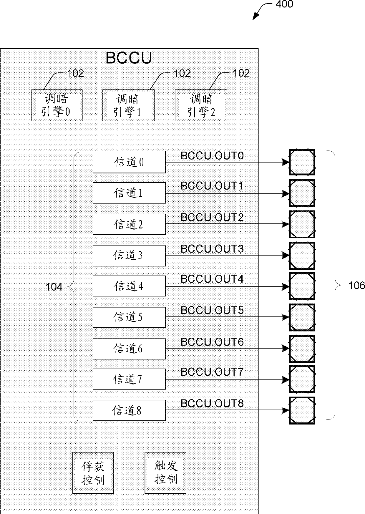
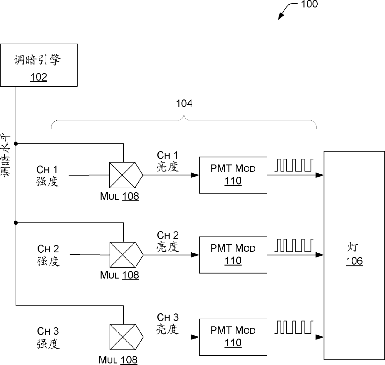
[0018] Representative implementations of devices and techniques provide means for modulating (or encoding, etc.) control signals. The modulated control signal can be used with a driver to vary the intensity of the light, change the color of the light, and more. For example, multiple control signals may be used to vary the intensity of multiple components of the lamp simultaneously, thereby changing the overall color and / or brightness of the lamp. The disclosed power message transfer (PMT) modulation device provides the driver with a modulated signal compatible with the driver and the system and carries the information of the input control signal.

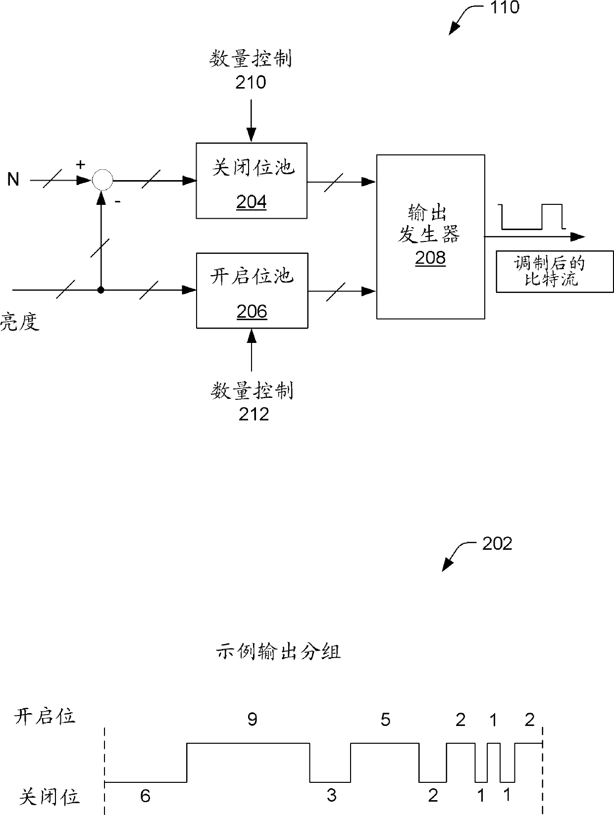
[0019] In an implementation, an input value is received at a PMT modulator (eg, a control signal generator). A modulated control signal with a varying rate of change may be generated by the PMT modulator based on the input value. For example, a modulated control signal generated based on an input value may be ...


PUM


Abstract

The invention relates a variable load driver with power message transfer. Representative implementations of devices and techniques provide a modulation arrangement for a control signal. The control signal is received as a digital value. A modulated control signal having a varying rate of change may be generated based on the quantity of off-bits and the quantity of on-bits of the digital value.

Description

technical field [0001] The present invention relates to variable load drives utilizing power messaging. Background technique [0002] With the proliferation of Light Emitting Diode (LED) lights, as well as other types of lights, there are many applications including dimming and changing the color of the lights. For example, it is often desirable for LED lights in residential and commercial applications to be dimmable (ie, have adjustable brightness). Additionally, it may be desirable for LED lights to have the ability to change color when used in instrumentation, user interface displays, and other information-related applications. Additionally, display screens for information or entertainment applications utilize LED lights that dim and / or change color. [0003] In some applications, a driver (which may be a switching driver, a linear driver, etc.) is used to control the current to the lamp. In such an arrangement the average current and thus the brightness of the lamp ca...

Claims


Application Information

Patent Timeline
IPC IPC(8): H05B37/02H05B44/00
CPCH04L49/00H05B37/00H05B33/0842H05B45/20H05B45/32H05B47/10H05B45/00H05B45/10D04C5/04D04C1/06
Inventor J.博里尔M.布克特A.拉本施泰因A.托马索维克斯
Owner INFINEON TECH AG
Why Eureka
Try Eureka