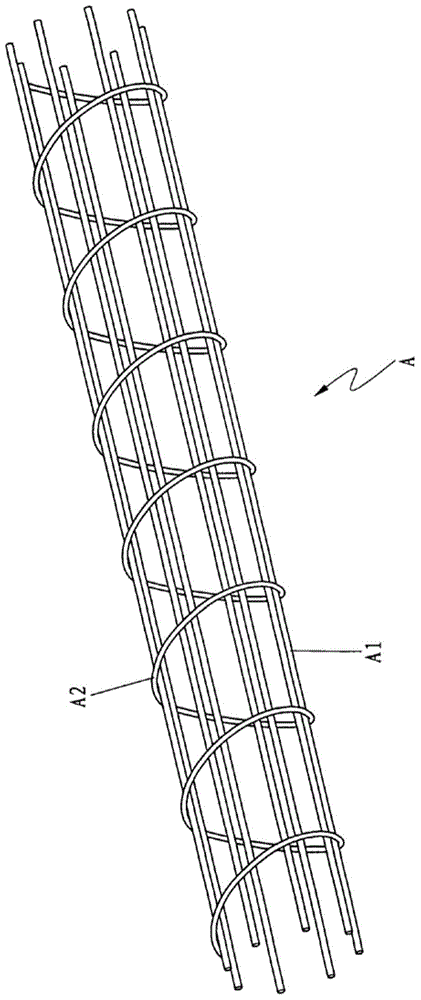
Rebar cage former

A steel cage forming machine and stirrup technology, which is applied in the field of construction machinery, can solve the problems of high cost, large area and low production efficiency of the reinforcing cage forming machine, so as to achieve a small footprint, improve bearing capacity and production efficiency. high effect

Inactive Publication Date: 2014-10-15
武汉侨志科技有限公司
View PDF6 Cites 24 Cited by
  • Summary
  • Abstract
  • Description
  • Claims
  • Application Information

AI Technical Summary

Problems solved by technology

[0004] In view of this, the present invention proposes a steel cage forming machine to solve the problem of steel cage production of retic

Method used


Image

  • Rebar cage former
  • Rebar cage former
  • Rebar cage former

Examples


Embodiment Construction

[0018] It should be noted that, in the case of no conflict, the embodiments of the present invention and the features in the embodiments can be combined with each other. The present invention will be described in detail below with reference to the accompanying drawings and examples.

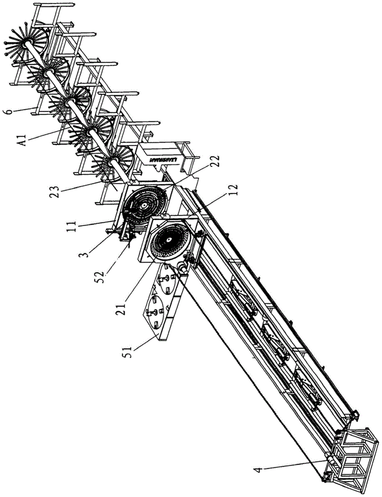
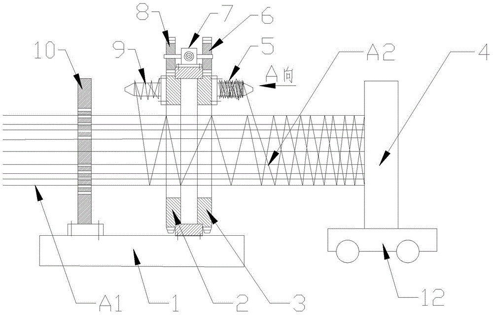
[0019] Such as image 3 and Figure 4 As shown, a preferred steel cage forming machine of the present invention includes a moving frame 4, two rotating frames 2, 3, a fixed frame 1, two stirrup pay-off devices 5, 9, a moving mechanism 12, and a rotating mechanism 7; A first fixed disk (not shown) is installed on the mobile frame 4, and a second fixed disk 10 is installed on the fixed frame 1. In the circumferential direction of the first fixed disk and the second fixed disk 10 A plurality of main reinforcement holes are arranged in different radial directions. The first fixed plate is used to fix one end of the main reinforcement A1, and the second fixed plate 10 is used to place and support t...


PUM


Abstract

The invention discloses a rebar cage former which comprises a moving frame, two rotating frames, a fixing frame, two stirrup pay-off devices, a moving mechanism, a rotating mechanism and a welding manipulator. A first fixing disc plate is mounted on the moving frame, the moving frame driven by the moving mechanism can linearly move along the X-axis direction, a second fixing disc plate is mounted on the fixing frame, the rotating frames are mounted on the fixing frame and positioned between the first fixing disc plate and the second fixing disc plate, the stirrup pay-off devices are mounted on the rotating frames respectively and rotate along with the rotating frames, the rotating mechanism can drive the rotating frames to rotate in opposite directions respectively, and the welding manipulator is mounted on the fixing frame. By the rebar cage former, rebar cages with netty spiral stirrups can be manufactured, load-bearing capacity of concrete columns can be improved. The rebar cage former is low in manufacturing cost, small in occupied area and high in manufacturing efficiency.

Description

technical field [0001] The invention relates to the field of engineering machinery, in particular to a steel cage forming machine. Background technique [0002] Such as figure 1 As shown, the reinforcement cage A is composed of the longitudinally stressed main reinforcement A1 and the one-way spiral stirrup A2. The one-way spiral stirrup A2 is mainly used to fix the main reinforcement A1 under longitudinal force, prevent the main reinforcement A2 from buckling and fix the position of the main reinforcement, improve the brittleness of concrete members, and form a skeleton with the main reinforcement A1 to ensure the rigidity of the skeleton and withstand The shear force caused by the horizontal load also acts to restrain the concrete in the core to increase the bearing capacity. [0003] Such as figure 2 As shown, at present, the reinforcement cage forming machine for making one-way spiral stirrups consists of a rotary drive mechanism, a main reinforcement fixer 21, a mai...

Claims


Application Information

Patent Timeline
IPC IPC(8): B21F31/00B21F1/02B21F27/10
Inventor 不公告发明人
Owner 武汉侨志科技有限公司
Why Eureka
Try Eureka