Screw guide structure in screwdriver for connecting screws

A technology for connecting screws and screws, applied in screwdrivers, manufacturing tools, wrenches, etc., can solve the problems of complicated screw removal operations, difficult to drive in positions, and screws are driven obliquely, so as to achieve easy and reduced screw removal operations. The front end of the equipment and the cheap effect of stamping processing

Active Publication Date: 2017-06-27
MAX CO LTD
View PDF1 Cites 1 Cited by
  • Summary
  • Abstract
  • Description
  • Claims
  • Application Information

AI Technical Summary

Problems solved by technology

[0003] However, in this screwdriver for connecting screws, when the head is pressed against the workpiece to be driven, the speed of the pressing device increases and the speed of screw feeding also increases. Therefore, the connecting screw being conveyed may exceed the specified position due to inertia, and the conveying action of the connecting screw may be defective.
When the driving operation is performed in this state, the axis of the screwdriver bit and the axis of the screw will be misaligned, so the screw will be driven in an oblique manner, and the front end of the screwdriver bit will not be aligned with the screw hole, causing the screw to deviate.
[0004] In addition, the screw tipping prevention mechanism disclosed in JP2008-119789A cannot solve the above-mentioned problems
That is, the screw tipping prevention mechanism of JP2008-119789A does not guide the posture of the screw before driving, so the problem of excessive delivery of the connecting screw cannot be avoided
When the driving action is performed directly under the condition that the excessively conveyed screw becomes inclined, the following problem will arise: the screw does not enter between a pair of tilting parts, but enters one side of the tilting part, and does not pass through the screw formed in the tilting part. If the hole in the center guides the posture and is punched obliquely, the protrusion will deviate
However, in the case of a box-shaped screw tipping prevention mechanism, it is difficult to confirm the driving position, and it is complicated to remove the screw when the screw is clogged.

Method used


Image

  • Screw guide structure in screwdriver for connecting screws
  • Screw guide structure in screwdriver for connecting screws
  • Screw guide structure in screwdriver for connecting screws

Examples


Embodiment Construction

[0079] Embodiments of the present invention will be described with reference to the drawings.

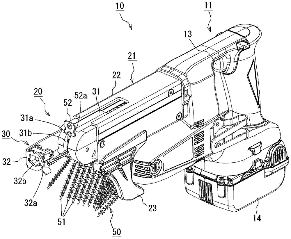
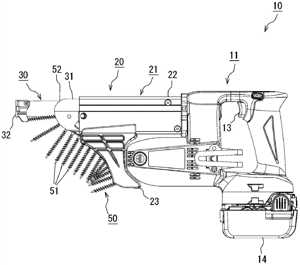
[0080] The screwdriver 10 according to this embodiment uses a connecting screw 50 in which a plurality of screws 51 are connected by a connecting band 52 . Such as figure 1 and figure 2 As shown, the screwdriver 10 includes a tool body 11 and a fastener supply device 20 attached to the tool body 11 .

[0081] The tool main body 11 includes a bit mounting portion at a front end portion covered by the fastener supply device 20 , and a screwdriver bit is mounted on the bit mounting portion. When the trigger 13 of the tool body 11 is pulled, an electric motor (not shown) rotates with a battery 14 as a power source. When the machine head part 30 is pressed to the driven part under the state of the motor rotation, the machine head part 30 is pressed in, the screwdriver bit bumps against and is held on the screw 51 of the machine head part 30, and the screwdriver bit is pressed. enter...


PUM


Abstract

A screw guide structure of a screw feeding mechanism of a screw driver (10) is provided. The screw feeding mechanism is configured to sequentially feed collated screws (50) to a driving position. The collated screws (50) are plurality of screws (51) connected by a connecting band (52). The screw guide structure includes a base part (24), a nose member (30) provided on a distal end of the base part (24) in a slidable manner, and a straight-driving guide member (41) supported by the nose member (30) in a displaceable manner so as to guide a screw (51) fed by the screw feeding mechanism to be in a straight posture. The straight-driving guide member (41) has a concave guide groove (41b) configured to guide a shaft (51a) of the screw (51). The straight-driving guide member (41) is configured and arranged such that the shaft (51a) of the screw (51) is engaged into the guide groove (41b) when the screw (51) is fed by the screw feeding mechanism, and such that the straight-driving guide member (41) is displaced when a head (51b) of the screw (51) passes by driving the screw (51) engaged into the guide groove (41b).

Description

technical field [0001] The present invention relates to a guide structure for vertically guiding screws in a screwdriver having a screw feeding mechanism that sequentially feeds connecting screws formed by connecting a plurality of screws with a connecting belt to a driving position. Background technique [0002] In a generally used screwdriver for connecting screws, the head is pushed in by pressing the head against the workpiece to be driven, and the feeding operation of the connecting screw and the driving operation of the connecting screw are performed in conjunction with this operation. As such a screwdriver, JP2008-119789A discloses a screw fall prevention mechanism that prevents the screw from falling. The screw tipping prevention mechanism has a pair of tilting members, and guides the screw vertically relative to the driving member by passing the screw through a hole formed between the pair of tilting members, thereby preventing the screw from tipping over. [0003]...

Claims


Application Information

Patent Timeline
Patent Type & Authority Patents(China)
IPC IPC(8): B25B23/04
CPCB25B23/045
Inventor 山本博纪竹村元田口聪
Owner MAX CO LTD
Why Eureka
Try Eureka