
Code printing device

A driving device and a coding technology, applied in printing, stamping, etc., can solve the problems of the coding device being uncomfortable and the machine head occupying a large space, etc., and achieve the effects of good stability, average force, and stable operation

Inactive Publication Date: 2014-10-15
BEIJING HENGLI TIEKE TECH DEV
View PDF13 Cites 4 Cited by
  • Summary
  • Abstract
  • Description
  • Claims
  • Application Information

AI Technical Summary

Problems solved by technology

[0004] For this reason, the technical problem to be solved by the present invention is to overcome the technical problem that the coding device in the prior art is not suitable for coding at a deeper position and the machine head needs to occupy a larger space, and provide a coding device suitable for coding at a deeper position. , and a coding device that can exchange font content and perform free coding at the same time

Method used


Image

  • Code printing device
  • Code printing device
  • Code printing device

Examples


Embodiment Construction

[0037] A coding device of the present invention is described in detail below in conjunction with specific embodiments:

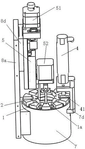
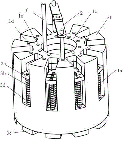
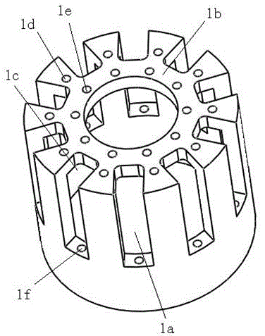
[0038] Such as figure 1 and figure 2 Shown is a coding device disclosed in the present invention, including a coding mechanism for changing codes, and an indenter device 4 for printing predetermined codes to preset positions, wherein the coding mechanism includes at least one A dial 1 with a hollow cylindrical structure, the dial 1 is provided with several installation grooves 1a along the axial direction; a driving rod 2 that drives the dial 1 to rotate around the central axis; and a word that is slidably connected to the dial 1 A code connection assembly, the character code connection assembly includes a blocking piece 3a located in the installation groove 1a, an elastic member 3b is arranged between the blocking piece 3a and the bottom of the installation groove 1a, and is located under the dial 1 The code block 3c on the side, and the connecting rod ...


PUM


Abstract

The invention discloses a code printing device, which comprises a code arrangement mechanism, wherein the code arrangement mechanism comprises at least one driving wheel, driving levers and a character code connecting component, wherein the driving wheel is constructed by a hollow cylinder and is provided with a plurality of mounting grooves along the axial direction; the driving levers drive the driving wheel to rotate along a center shaft; the character code connecting component is connected to the driving wheel in a sliding manner, the character code connecting component comprises blocking pieces, elastic pieces, character code blocks and connecting rods, wherein each blocking piece is positioned in the corresponding mounting groove; each elastic piece is arranged between each blocking piece and the bottom of the corresponding mounting groove; the character code blocks are positioned on the lower side of the driving wheel; the connecting rods are respectively fixedly connected to the blocking pieces and the character code blocks, and each connecting rod penetrates between each mounting groove and the bottom surface of the driving wheel. The code printing device solves the technical problems that the code printing device in the prior art is not suitable for code printing in a deeper position and a machine head needs to occupy a larger space, and the code printing device capable of freely encoding while exchanging the contents of a matrix is provided.

Description

technical field [0001] The invention belongs to the field of hard printing equipment, in particular to a coding device. Background technique [0002] Sand mold coding often has a variety of digits. In the existing technology, when typing or coding operations in the process, manual operation is required to change characters, which affects the continuity of the coding process. Perform casting to form digital codes, and manually code the prefixes, which wastes manpower and is cumbersome to operate. Although the existing roller type coding machines can realize mechanized coding, their mechanical volume is relatively large. During the coding process, it is necessary to Putting the entire device close to the coding area takes up a lot of space, especially not suitable for coding operations in small and deep areas. [0003] Chinese patent document CN200960770Y discloses a coder, which realizes printing numbers on molding materials by designing wheel discs with different digits on ...

Claims


Application Information

Patent Timeline
IPC IPC(8): B41K3/04B41K3/62
Inventor 裴荟蓉宫明远马永存李新宁曹贵伟
Owner BEIJING HENGLI TIEKE TECH DEV
Learn More