
A kind of intake manifold and automobile engine

A technology of intake manifold and air inlet, applied in engine components, machines/engines, mechanical equipment, etc., can solve the problem of reducing the uniformity of pressure loss, not conducive to reducing intake pressure loss, affecting the maximum power and maximum torque of the engine, etc. question

Active Publication Date: 2016-03-16
GUANGZHOU AUTOMOBILE GROUP CO LTD
View PDF5 Cites 0 Cited by
  • Summary
  • Abstract
  • Description
  • Claims
  • Application Information

AI Technical Summary

Problems solved by technology

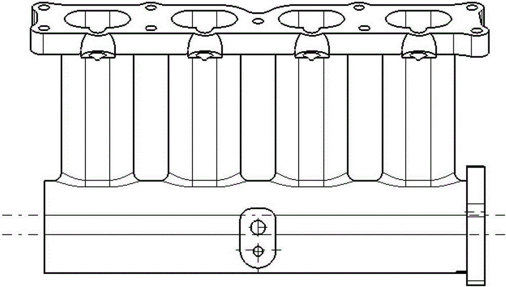
[0003] like figure 1 Shown is a schematic diagram of the structure of an intake manifold in the prior art. The air passage structure of the intake manifold is unreasonably designed, and the cross-sectional structure of the equal pressure chamber is used, which is not conducive to reducing the intake pressure loss; The structure is not conducive to avoiding the characteristics of uneven pressure loss of each cylinder due to the disadvantages of the airway space structure, that is, the uniformity of the pressure loss of each airway is poor, thus affecting the uniformity of the intake air volume of each cylinder of the engine
Therefore, unreasonable airway structure design will increase the intake pressure loss and reduce the uniformity of pressure loss, affect the maximum power and maximum torque of the engine, and the uniformity of the work of each cylinder, and ultimately affect the performance of the engine

Method used


Image

  • A kind of intake manifold and automobile engine
  • A kind of intake manifold and automobile engine
  • A kind of intake manifold and automobile engine

Examples


Embodiment Construction

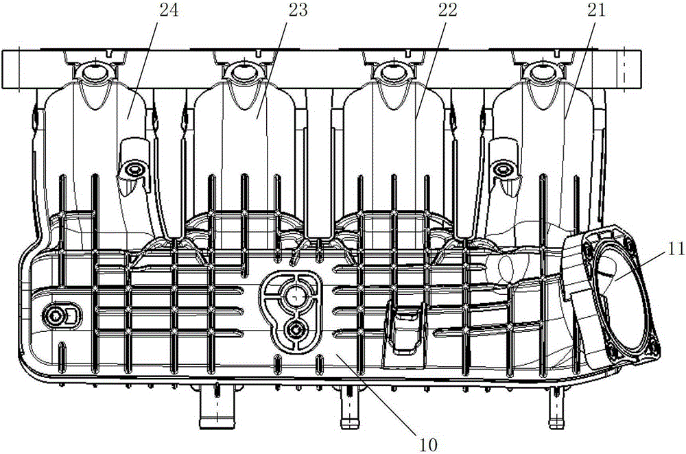
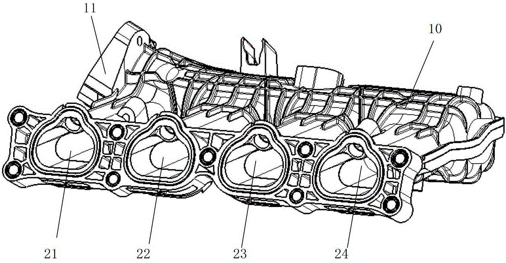
[0030] like Figure 2 to Figure 7 As shown, in order to solve the problems of unreasonable design of intake manifold airway structure, large intake pressure loss and poor intake uniformity in the prior art, the embodiment of the present invention provides an intake manifold, including a plenum chamber 10 and At least two air passages (such as air passages 21, 22, 23, 24) communicating with the pressure stabilizing chamber 10, and the air inlet 11 for connecting with the throttle valve is provided on the stabilizing chamber 10, wherein, the air passage and the stabilizing chamber The junction of the chamber 10 adopts an unequal rounded structure that allows the gas to be evenly distributed to each air channel after being stabilized in the pressure stabilizing chamber through the air inlet. The unequal fillet structure adopts unequal fillet radii at the transition joint between the air passage and the plenum chamber 10 . The airway structure is designed with unequal rounded cor...


PUM


Abstract

The invention provides an air inlet manifold and an automobile engine comprising the air inlet manifold. The air inlet manifold comprises a pressure stabilizing cavity and at least two air channels which are communicated with the pressure stabilizing cavity, wherein the pressure stabilizing cavity is provided with an air inlet connected with a throttle valve; the joints of the air channels and the pressure stabilizing cavity have unequal filleted structures by which air is uniformly distributed into each air channel after passing through the air inlet and being subjected to pressure stabilization in the pressure stabilizing cavity. Preferably, at the joints of the air channels and the pressure stabilizing cavity, the fillet of a single air channel vertical to the air inlet direction is greater than a fillet in the air inlet direction; at the joints of the air channels and the pressure-stabilizing cavity, the fillet of a first air channel in the air inlet direction is greater than the fillet of a tail air channel, and the fillet of a middle air channel is smaller than the fillets of the first air channel and the tail air channel. By adopting the structure, the air inlet pressure loss can be reduced effectively, the difference among the pressure loss of each air channel is lowered, the air inflow of each cylinder kept uniform while the air inflow of each cylinder is increased, and the power performance and economical efficiency of the engine are improved and increased.

Description

technical field [0001] The invention relates to the technical field of automobile engines, in particular to an intake manifold and an automobile engine including the intake manifold. Background technique [0002] The airway structure of the intake manifold is one of the main factors affecting the intake air volume and uniformity of the engine. The maximum air intake of each cylinder of the engine is the premise to ensure the realization of the highest power of the engine; and the uniformity of the intake air of each cylinder directly affects the uniformity of the working ability of each cylinder of the engine. Poor uniformity will result in unstable torque output and large engine vibration. The problem is that at the same time, in order to limit the large knocking phenomenon of individual cylinders, the ignition advance angle of the engine will be reduced as a whole, and the overall output capacity of the engine will be reduced. Therefore, a reasonable design of the airway ...

Claims


Application Information

Patent Timeline
Patent Type & Authority Patents(China)
IPC IPC(8): F02M35/104
Inventor 黄英铭孙凡嘉朱宏飞黄初华
Owner GUANGZHOU AUTOMOBILE GROUP CO LTD
Learn More