Method used for measuring pose of non-cooperative target based on complete light field camera

A non-cooperative target and pose measurement technology, which is applied in the field of 3D vision target pose measurement, can solve the problems that cannot be eliminated, affect the real-time measurement, and the measurement distance is short.

Inactive Publication Date: 2014-10-15
HEFEI UNIV OF TECH
View PDF6 Cites 27 Cited by
  • Summary
  • Abstract
  • Description
  • Claims
  • Application Information

AI Technical Summary

Problems solved by technology

[0006] 1. Based on monocular vision and auxiliary feature measurement, the point and line features on the circular surface are used for pose estimation. The geometric information in the coordinate system, then the false solution obtained by traditional monocular vision cannot be eliminated.
[0007] 2. For the measurement method based on binocular stereo vision, it is necessary to use the images acquired by the left and right cameras to estimate the pose information of the circle, which greatly affects the real-time performance of the measurement
[0008] 3. For the pose measurement method based on the depth sensor, the output image is noisy, the resolution is low, and the measurement distance is short, so it is impossible to obtain long-distance non-cooperative target pose information
[0009] 4. The current vision-based circular pose measurement method is easy to lose focus when shooting non-cooperative targets, which brings blurred target images

Method used


Image

  • Method used for measuring pose of non-cooperative target based on complete light field camera
  • Method used for measuring pose of non-cooperative target based on complete light field camera
  • Method used for measuring pose of non-cooperative target based on complete light field camera

Examples


Embodiment Construction

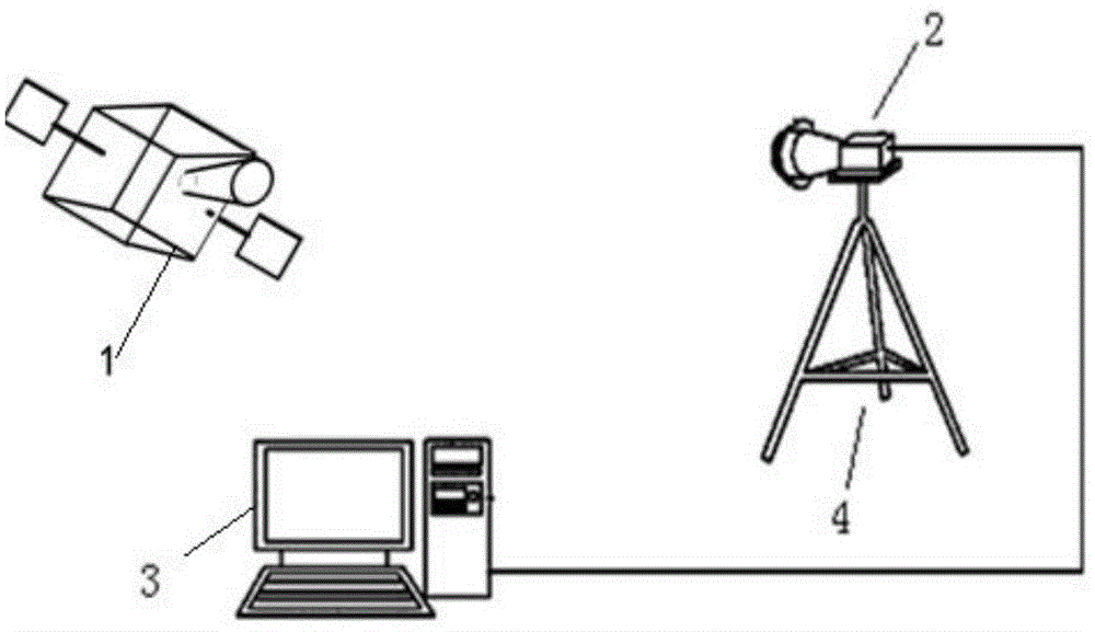
[0083] In this embodiment, a non-cooperative target pose measurement method based on a full light field camera is applied to a non-cooperative target pose measurement system based on a full light field camera, see figure 1 The system consists of a non-cooperative target 1, a full-light-field camera 2, a PC 3 for the pose measurement data processing system, and a camera holder 4 for fixed installation of the full-light-field camera 2; the non-cooperative target 1 is located at the angle of view of the full-field camera 2. Within the range, the non-cooperative target includes the star and arrow docking ring; the star and arrow docking ring on the non-cooperative target is used as the identification object, and the star and arrow docking ring on the non-cooperative target is a circular feature;

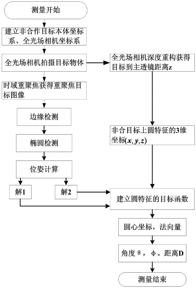
[0084] See figure 2 , The non-cooperative target pose measurement method based on the full-field camera is as follows:

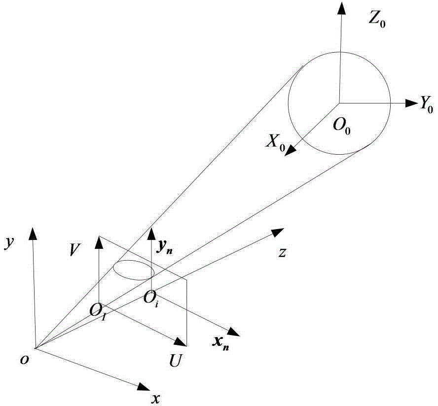
[0085] Step 1, such as image 3 As shown, take the center of the circ...


PUM


Abstract

The invention discloses a method used for measuring the pose of a non-cooperative target based on a complete light field camera. The method is applied in the non-cooperative target containing a star arrow docking ring. The star arrow docking ring on the non-cooperative target is a circle and is characterized in that step 1, the light field image of the non-cooperative target with circular features is obtained by adopting the compete light field camera; step 2, surface normal vectors, and the coordinates of the circular center of the circular features are calculated in the main lens coordinate system of the complete light field camera; step 3, false solutions are removed; step 4, the pose of the non-cooperative target is acquired. According to the invention, the false solutions based on the monocular vision pose estimations of the circle can be effectively removed, so that the pose of the non-cooperative target which meets accuracy requirements can be obtained.

Description

Technical field [0001] The invention relates to a non-cooperative target pose measurement method based on a full-light field camera, belonging to the field of three-dimensional vision target pose measurement. Background technique [0002] With the continuous development of computer vision technology, computer vision-based pose measurement is an important issue in many research fields such as modern navigation, tracking, and control, and it is highly valued in various fields such as national defense, aerospace, aviation, industry, and medicine. In the field of aerospace, most of the spacecraft that are already in orbit are non-cooperative targets, so the relative pose measurement of non-cooperative targets has become the key to in-orbit service technology. For most non-cooperative targets, there is generally a star-and-arrow docking ring structure, which can provide a single circle feature, but the traditional monocular visual pose estimation based on the circle has two pose solut...

Claims


Application Information

Patent Timeline
Patent Type & Authority Applications(China)
IPC IPC(8): G01C11/00G01C21/00
CPCG01C11/00G01C21/00
Inventor 张旭东胡良梅高隽陈欣王一李梦娜徐小红涂义福许林
Owner HEFEI UNIV OF TECH
Why Eureka
Try Eureka