
Rotation laser having lens which is deformable in a targeted manner by actuators
A technology of rotating lasers and actuators, applied in active optical measurement devices, instruments, optics, etc., can solve the problems of increased susceptibility to maintenance, high weight of rotating lasers, slow mechanical displacement of lenses, etc. The effect of leveling fittings, simplified construction
Patent Information
- Authority / Receiving Office
- CN · China
- Patent Type
- Applications(China)
- Current Assignee / Owner
- Publication Date
- 2014-10-15
Smart Images
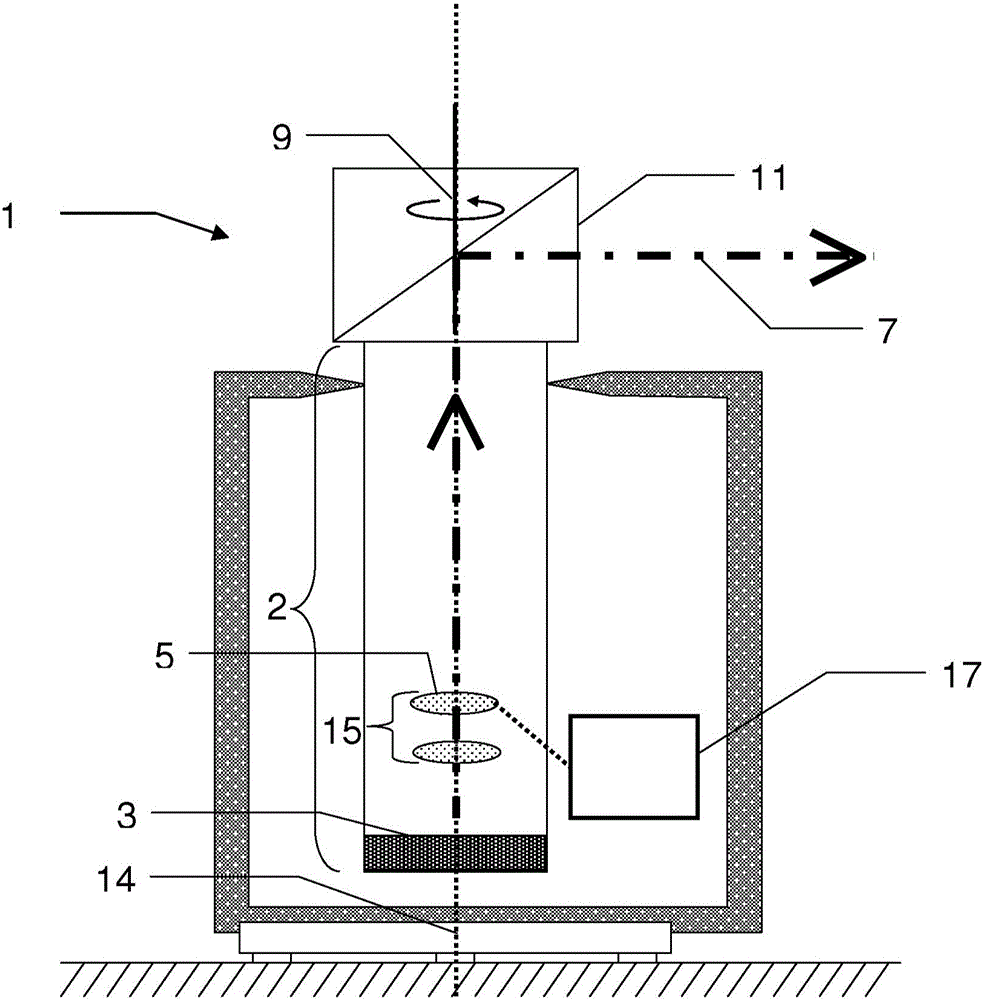
Figure 1 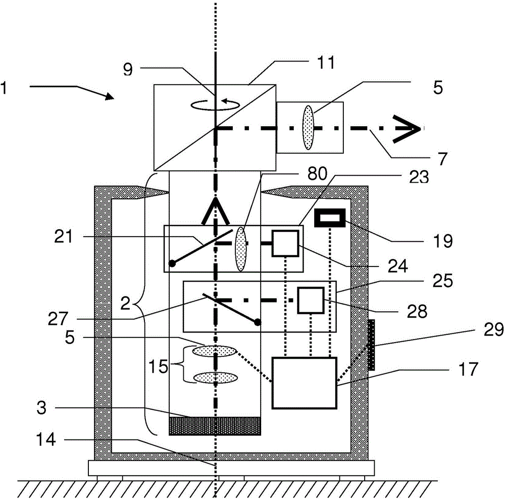
Figure 2 
Figure 3
Abstract
Description
technical field
[0001] The invention relates respectively to a rotating laser, to a laser system comprising a rotating laser and a laser receiver and to a method for steering a laser beam achievable by a rotating laser, respectively. Background technique
[0002] Rotating lasers for marking points and for defining reference lines on reference planes or objects such as walls, floors or ceilings on construction sites have been used for many years in the industrial sector and in residential and construction. They can be used to project horizontal planes, vertical planes, or planes inclined in a defined manner, which aid in orienting or positioning objects.
[0003] Rotary lasers generally comprise a transmitting unit comprising a laser light source for generating a laser beam. Furthermore, the rotating laser has an optical system comprising one or more lenses, and deflection means rotatable about the axis of rotation and used for directed emission of the laser beam. If a rota...
Examples
Embodiment Construction
[0076] figure 1 An embodiment of the rotation laser 1 according to the invention is schematically shown in side view. The rotation laser 1 comprises a transmission unit 2 and a deflection device 11 . The sending unit 2 comprises a laser light source 3 , for example a laser diode, for generating a laser beam 7 . In this example, an optical system 15 comprising one or more lenses is also provided in the sending unit 2, and the lenses are arranged along the optical axis 14 of the sending unit so that, ideally, the laser beam emitted by the laser light source 3 The axis of 7 coincides with the optical axis of the sending unit 4 . The optical system 15 is arranged between the laser light source 3 and the deflection device 11 . The deflection device 11 is used for directed emission of the laser beam 7 and is mounted rotatably about an axis of rotation 9 which ideally coincides with the optical axis of the transmitting unit and the axis of the laser beam 7 . The deflection devic...