Crankshaft kinetic analysis method

A dynamic analysis and crankshaft technology, applied in special data processing applications, instruments, electrical digital data processing, etc., can solve problems such as difficult convergence of calculations, large number of grids, and problematic 3D grid quality, and achieve calculation and solution time Short, builds fast, reduces time for effects

Active Publication Date: 2014-10-15
SAIC-GM-WULING AUTOMOBILE CO LTD
View PDF3 Cites 6 Cited by
  • Summary
  • Abstract
  • Description
  • Claims
  • Application Information

AI Technical Summary

Problems solved by technology

[0004] 1. Use one-dimensional analysis method to simplify the crankshaft, which cannot reflect the structural information of the crankshaft in detail;
[0005] 2. To use a complete three-dimensional analysis method, it is necessary to establish a FEM finite element model of the engine. Complex parts such as cylinder blocks, cylinder heads, crankshafts, etc. are time-consuming to divide finite element meshes and mesh assembly; the number of meshes is large, and the finite element The grid quality is also difficult to guarantee; with a huge number of grids, the finite element analysis takes a long time; the finite element calculation is difficult to converge, and the analysis is prone to failure
[0006] 3. When meshing the crankshaft, first perform 2D meshing on the crankshaft, and then generate a 3D mesh. 2D meshing is time-consuming, and the quality of the 3D mesh is problematic. Multiple adjustments to the 2D mesh are required , takes a long time

Method used


Image

  • Crankshaft kinetic analysis method
  • Crankshaft kinetic analysis method
  • Crankshaft kinetic analysis method

Examples


Embodiment Construction

[0034] The present invention will be further described below in conjunction with the accompanying drawings and specific embodiments.

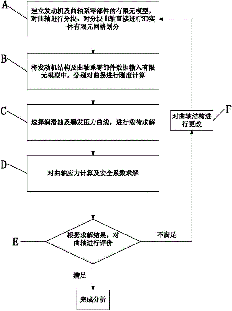
[0035] Such as figure 1 Shown, the present invention provides a kind of crankshaft dynamics analysis method, comprises the following steps:

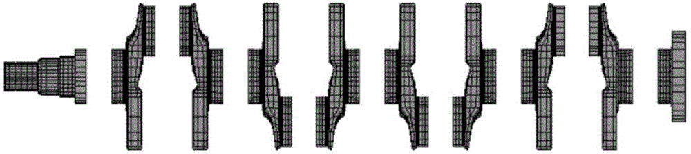
[0036] A. Establish the finite element model of the engine and crankshaft parts, divide the crankshaft into blocks, and directly perform 3D solid finite element mesh division on the block crankshaft; in order to ensure the accuracy of stress calculation, the mesh division needs to be finer in the fillet area denser; the grid division includes: 1. Import the crankshaft model into Hypermesh, and take the center plane of the main journal and the connecting rod journal, such as figure 2 As shown, the crankshaft is divided into blocks.

[0037] 2. Select tetramesh in 3D, select Volume Tetra to directly perform 3D solid mesh division on the crankshaft block, thus avoiding the traditional division of 2D grid ...


PUM


Abstract

The invention relates to the field of engines, in particular to a crankshaft kinetic analysis method. The method includes the steps of A, building finite element models of an engine and crankshaft system parts, partitioning a crankshaft, and directly performing 3D entity finite element meshing on the partitioned crankshaft; B, inputting the engine structure and crankshaft system part data into the finite element models, and respectively performing rigidity calculation on crank throw; C, selecting a lubricant and explosion pressure curve to perform load calculation; D, calculating crankshaft stress and safety coefficient; E, evaluating the crankshaft according to calculation results. The crankshaft kinetic analysis method has the advantages that the method is fast, high in efficiency and high in reliability, and time is reduced greatly; fast and efficient 3D meshing of the crankshaft is achieved, analysis model building is fast, and the analysis models are fast in response; calculation time is short; the method is more accurate as compared with a one-dimensional method and faster as compared with a complete three-dimensional method.

Description

technical field [0001] The invention relates to the field of engines, in particular to a crankshaft dynamics analysis method. Background technique [0002] The crankshaft is one of the most important parts of the engine. Its size parameters not only affect the overall size and weight of the engine to a large extent, but also affect the reliability and life of the engine to a large extent. Destruction of the crankshaft may cause serious damage to other components and the engine. At the beginning of engine design and development, it is necessary to evaluate the crankshaft structure, size parameters, materials and processes as soon as possible. Therefore, fast, efficient and accurate dynamic analysis of crankshaft stress and safety factor is very important in the conceptual design stage of the engine. [0003] In the traditional crankshaft dynamics analysis, there are the following problems: [0004] 1. Use one-dimensional analysis method to simplify the crankshaft, which ca...

Claims


Application Information

Patent Timeline
Patent Type & Authority Applications(China)
IPC IPC(8): G06F17/50
Inventor 王磊穆建华叶年业唐海娇黄勇和
Owner SAIC-GM-WULING AUTOMOBILE CO LTD
Why Eureka
Try Eureka