Antenna and array antenna

An antenna and array technology, which is applied in the field of mobile communication antennas, can solve the problems of increasing production difficulty and cost, not reaching 28dB, and greatly affecting the isolation degree, and achieves improved isolation and cross-polarization ratio, good consistency, Effect of Impedance Bandwidth Improvement

Inactive Publication Date: 2014-10-15
GCI SCI & TECH
View PDF2 Cites 10 Cited by
  • Summary
  • Abstract
  • Description
  • Claims
  • Application Information

AI Technical Summary

Problems solved by technology

[0004] The vibrator arm of this structure enables a single radiating unit to meet the requirements, but when forming an array (the array is usually composed of 2 to 10 radiating units), it has a great influence on the isolation. Often the isolation after forming the array is only about 22dB. Far below the requirement of 28dB
Therefore, it is necessary to add various sheet and strip metal sheets between the radiating units or under the vibrator arms to barely solve the problem of isolation, but it increases the difficulty and cost of production

Method used


Image

  • Antenna and array antenna
  • Antenna and array antenna
  • Antenna and array antenna

Examples


Embodiment Construction

[0021] The following will clearly and completely describe the technical solutions in the embodiments of the present invention with reference to the accompanying drawings in the embodiments of the present invention. Obviously, the described embodiments are only some, not all, embodiments of the present invention. Based on the embodiments of the present invention, all other embodiments obtained by persons of ordinary skill in the art without creative efforts fall within the protection scope of the present invention.

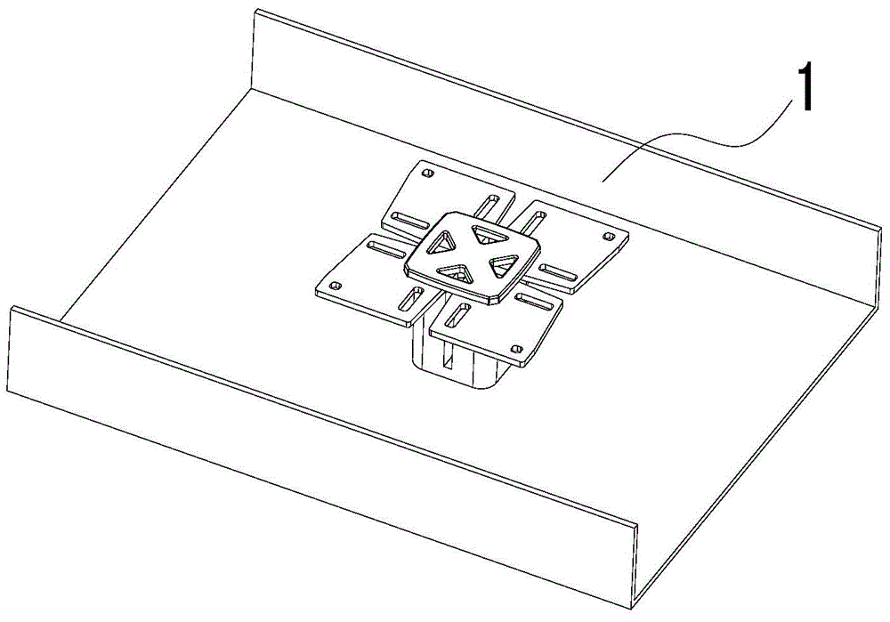
[0022] see figure 2 , is a schematic three-dimensional structure diagram of an embodiment of the antenna provided by the present invention.

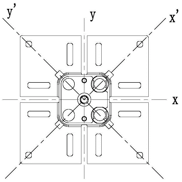
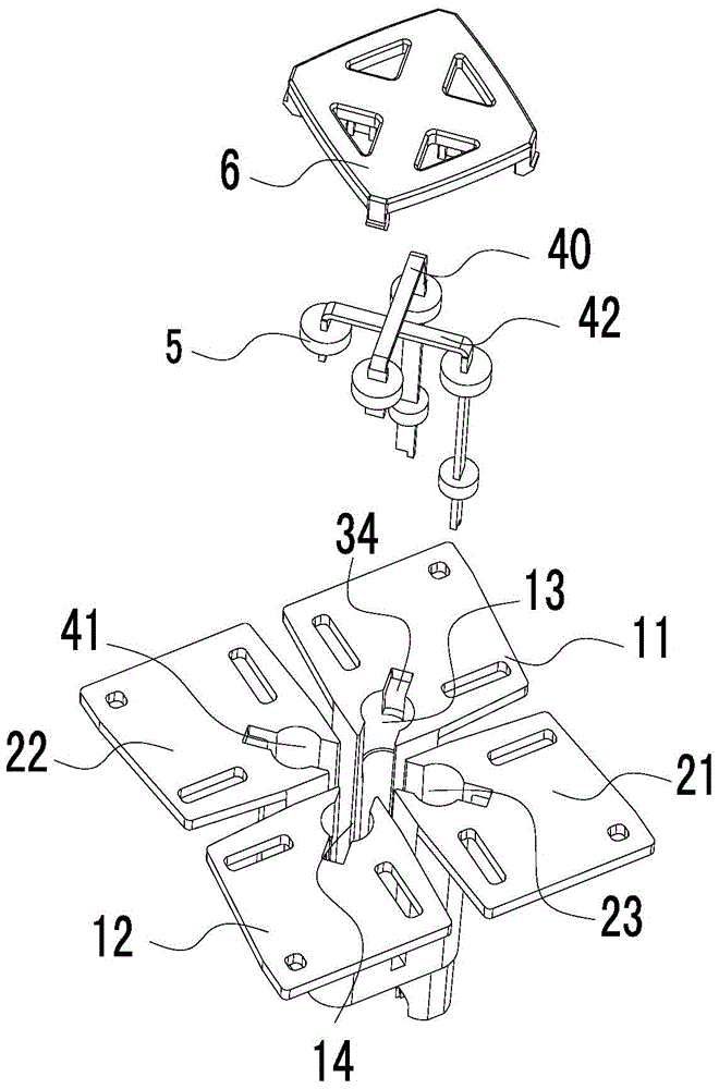
[0023] This embodiment provides an antenna, including a broadband dual-polarization radiation unit and a reflection plate. Such as Figure 3-8 As shown, the broadband dual-polarized radiation unit includes a support 9 and four dipole arms of different shapes;

[0024] The four vibrator arms are located on the same plane, ...


PUM


Abstract

The invention discloses an antenna. The antenna comprises a broadband dual-polarized radiation unit and a reflecting plate, wherein the broadband dual-polarized radiation unit comprises a support part and four vibrator arms in different shapes; the four vibrator arms are located at the same plane and arranged in an array with two rows and two columns to form two pairs of orthogonally polarized dipoles; as the diagonal line of the array serves as an axis, the four vibrator arms are in an asymmetric structure with respect to the axis; the vibrator arms are of hollow quadrangular structures; the four vibrator arms are connected with the four corners of the support part; the support part is located below the vibrator arms and is vertical to the plane of the vibrator arms; each vibrator arm is provided with a clipped corner near the corner part in the center of the array, and is connected with a corner part of a corresponding support part at the clipped corner; the support part is of a hollow structure; a groove with equal height and equal width is formed in the middle part of each wall surface of the support part. With the adoption of the embodiment of the invention, impedance bandwidth of single radiation unit can be increased efficiently, and the isolation degree and the cross polarization ratio of the radiation unit are improved.

Description

technical field [0001] The invention relates to the technical field of mobile communication antennas, in particular to an antenna and an array antenna. Background technique [0002] In recent years, the 4G communication technology dominated by LTE has developed very rapidly, and the domestic market is about to enter the commercial stage. The market demand for 1710-2690MHz broadband base station antennas that can cover multiple frequency bands is increasing. Base stations working at this frequency The antenna can cover frequency bands such as DCS (1710-1880MHz), PCS (1850-1990MHz), UMTS (1920-2170MHz), TD-SCDMA (1880-2690MHz) and WIMAX and WIFI (2400-2500). The performance of the antenna radiating unit basically determines the performance of the array antenna, and the relative bandwidth of 1710-2690MHz reaches 44%, which requires the antenna radiating unit to have ultra-wideband performance, and puts forward higher requirements for impedance matching and isolation. [0003] ...

Claims


Application Information

Patent Timeline
Patent Type & Authority Applications(China)
IPC IPC(8): H01Q1/36H01Q1/12H01Q1/50H01Q19/10H01Q21/00H01Q21/24H01Q1/52
Inventor 詹敏峰陈韶明
Owner GCI SCI & TECH
Why Eureka
Try Eureka