D2d communication in wireless networks

A technology of wireless communication and wireless communication system, applied in the field of D2D (device-to-device) link, which can solve problems such as conflicts

Inactive Publication Date: 2014-10-15
FUJITSU LTD
View PDF4 Cites 42 Cited by
  • Summary
  • Abstract
  • Description
  • Claims
  • Application Information

AI Technical Summary

Problems solved by technology

In RA-based mode, UE randomly selects any preamble, and if two or more UEs accidentally select the same preamble, there is a risk of "collision" at the eNB

Method used


Image

  • D2d communication in wireless networks
  • D2d communication in wireless networks
  • D2d communication in wireless networks

Examples


Embodiment Construction

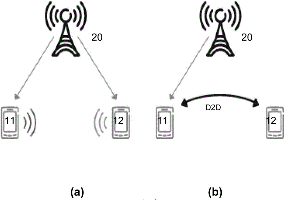
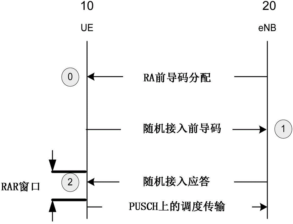
[0111] The RACH procedure introduced in the background includes communication between UE and eNB. For the purpose of being able to announce, establish and modify parameters of D2D communication, the specific embodiments of the present invention relate to details of RACH procedure improvement. Hereinafter, a "D2D capable UE" is defined as a UE that has the capability of broadcasting the possibility (announcement) of a D2D link with other UEs and is capable of acting as a relay for traffic from or to at least one other UE. For clarity, other UEs will be referred to as D2D-requiring UEs. therefore, figure 1 UE11 in (b) is an example of a D2D-capable UE, and U12 is a D2D-needing UE.

[0112] A UE may determine whether it is a D2D-capable UE based on factors such as the UE's inherent capabilities and its current load (data buffering status), battery level, and quality of its wireless link (channel) with the eNB. Measurements such as Received Channel Strength Indication (RSSI) ca...


PUM


Abstract

The invention relates to Device-to-Device (D2D) communication in wireless networks. In a wireless communication network, a D2d link is set up using a modified Random Access (RACH) procedure. The conventional RACH procedure is modified to enable a D2D-capable UE (11) to indicate its capability to other UEs (12), to receive additional information from a base station (20), and to enable the handshake procedure used to establish a D2D link. Broadcast system information may additionally be modified to enable D2D links between UEs (11, 12) in the same or different coverage areas, taking into consideration the RRC UE states (RRC_Connected or RRC_Idle). The proposed modifications to the broadcast system information include: an indication of D2D link opportunities with other UEs under a different coverage area to that of the D2D capable UE; and RACH parameters in the coverage area of the D2D capable UE, to indicate the listening period for the D2D link.

Description

technical field [0001] The present invention relates to wireless communication networks such as those compatible with the 3GPP Long Range Evolution (LTE) and 3GPP LTE-A (LTE-Advanced) groups of standards, and more particularly to so-called D2D (Device-to-Device) links of such networks. Background technique [0002] Wireless communication networks are widely known as figure 1 (a) Exemplarily shown, a base station BS20 utilizes a given radio access technology RAT to communicate with user equipments UE11 and 12 (also referred to as terminals, subscribers or mobile stations) located within the coverage area (cell) of the BS. figure 1 The arrows in (a) indicate the data paths between the base station BS20 and each of the UEs 11 and 12 . Although not shown, in practice there would also be a separate control path for notifications in the network regarding management and general information, as opposed to the data transported on the data path for providing services to users of. T...

Claims


Application Information

Patent Timeline
Patent Type & Authority Applications(China)
IPC IPC(8): H04W16/14H04W72/04
CPCH04W4/06H04W72/042H04W72/005H04W76/023H04W8/005H04W74/08H04W74/002H04W76/14H04W72/23H04W72/30
Inventor M·特萨诺维奇P·巴克内利H·谢波
Owner FUJITSU LTD
Why Eureka
Try Eureka