Solar power dual full bridge injection phase-locked power synthesis metal halide lamp

A solar power supply, injection phase-locked technology, applied in the direction of electric light source, light source, electrical components, etc., can solve the problems of unstable oscillation frequency power, unbalanced light power amplitude, shortened service life, etc., to avoid oscillation frequency change power imbalance , Avoid the temperature rise of the device and prolong the service life

Active Publication Date: 2016-08-24
常州勤行电子科技有限公司
View PDF8 Cites 0 Cited by
  • Summary
  • Abstract
  • Description
  • Claims
  • Application Information

AI Technical Summary

Problems solved by technology

[0002] Electronic ballasts in the prior art usually use LC or RC oscillators as the electric light source of metal halide lamps, and the oscillation frequency generated is affected by the poor stability of temperature changes and the power is not stable enough, resulting in a decrease in light intensity. Although the structure is simple and the cost is low
In order to obtain high-power lighting, it is necessary to increase the current, so that the power consumption of the oscillating power tube will increase sharply and the temperature will rise too high. The oscillation frequency will change, and the result will be that the power amplitude of the light will be unbalanced with the frequency change.
At the same time, when the large current passes through the coil, the temperature rises and the magnetic permeability decreases, and the magnetic saturation inductance becomes smaller and the impedance tends to zero. The working time of the lamp is proportional to the temperature rise, and the temperature rise accelerates the aging of the device. Burning out components shortens service life

Method used


Image

  • Solar power dual full bridge injection phase-locked power synthesis metal halide lamp
  • Solar power dual full bridge injection phase-locked power synthesis metal halide lamp
  • Solar power dual full bridge injection phase-locked power synthesis metal halide lamp

Examples


Embodiment Construction

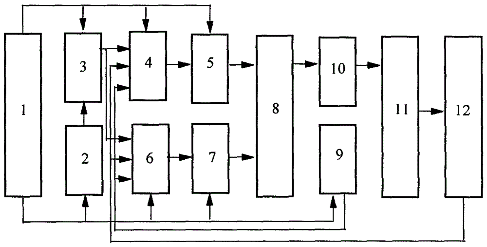
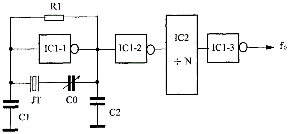
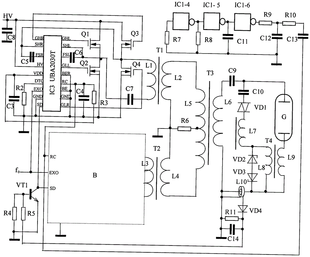
[0013] refer to figure 1 , 2 , 3, 4( image 3 Taking the self-oscillating chip and the full-bridge inverter A circuit as an example, the self-oscillating chip and the full-bridge inverter B are the same), the specific implementation mode and embodiment of the present invention: including a solar power supply 1, a metal halide lamp tube 11, a reference crystal oscillator 2. Frequency divider 3. Two self-oscillating chips 4, 6. Full-bridge inverter A5, full-bridge inverter B7, summing coupler 8, FM signal generator 9, lamp trigger circuit 10, lamp Abnormal current detector 12, wherein the reference crystal oscillator 2 is composed of a quartz crystal resonator JT, two inverter ICs 1-1 , IC 1-2 and resistance R 1 , capacitance C 0 、C 1 、C 2 composition, the first inverter IC 1-1 The bias resistor R is connected across the input and output terminals 1 , and respectively connected to the ground capacitor C 1 、C 2 , meanwhile, also across the series trimmer capacitor C 0...


PUM


Abstract

The invention relates to the technical field of electric light source illumination and specifically discloses a solar power supply double-full-bridge injection-locking phase power synthesis metal halide lamp. Two RC oscillators are together connected to a resistor R11 and a capacitor C14 for synchronous oscillation. A self-sustained oscillation chip 4, an output power transformer T1of a full-bridge inverter A, a self-sustained oscillation chip 6, and an output power transformer T2 of a full-bridge inverter B are fed into an addition coupler in a reverse-phase way for power synthesis. The synthesized power further undergoes a voltage boost and is then fed into a lamp tube trigger circuit for turning a lamp tube on. Signals of a reference crystal oscillator are injected into the two self-sustained oscillation chips 4, 6 through a frequency divider for phase locking. Large-power illumination is achieved. Excessive temperature rise of the device, changes of oscillation frequency, imbalanced power and dim light are avoided. Triangular wave signals of a frequency modulation signal generator are accessed to the two self-sustained oscillation chips 4, 6 for suppressing light scintillation in a frequency modulation way. Signals of a lamp tube abnormal current detector are accessed to SD ends of the two self-sustained oscillation chips 4, 6 through a triode. Oscillation is rapidly stopped. Power MOS tubes of the full-bridge inverters are further turned off. The metal halide lamp is suitably used in large-power metal halide lamp illumination occasions.

Description

technical field [0001] The invention relates to the technical field of electric light source lighting, in particular to a metal halide lamp with dual full-bridge injection of solar power and phase-locked power synthesis. Background technique [0002] Electronic ballasts in the prior art usually use LC or RC oscillators as the electric light source for metal halide lamps, and the oscillation frequency generated is affected by poor temperature stability and the power is not stable enough, resulting in a decrease in light intensity. Although the structure is simple and the cost is low. In order to obtain high-power lighting, the current must be increased, and the power consumption of the oscillating power tube will increase sharply and the temperature will rise too high. The oscillation frequency will change, and as a result, the power amplitude of the light will be unbalanced with the frequency change. At the same time, when the large current passes through the coil, the tempe...

Claims


Application Information

Patent Timeline
Patent Type & Authority Patents(China)
IPC IPC(8): H05B41/285
CPCY02B20/00
Inventor 阮树成
Owner 常州勤行电子科技有限公司
Why Eureka
Try Eureka