Rock-core drill holder

A technology of core drilling rigs and grippers, which is applied to drill pipes, drill pipes, drilling equipment, etc., and can solve the problems of time and manpower, cost, and inconvenient operation

Inactive Publication Date: 2014-10-22
ATLAS COPCO (NANJING) CONSTR & MINING EQUIP CO LTD
View PDF4 Cites 3 Cited by
  • Summary
  • Abstract
  • Description
  • Claims
  • Application Information

AI Technical Summary

Problems solved by technology

The slips of this type of gripper are inside the gripper box. When it is necessary to replace different types of slips, the operation is inconvenient and takes a lot of time and manpower.

Method used


Image

  • Rock-core drill holder
  • Rock-core drill holder
  • Rock-core drill holder

Examples


Embodiment Construction

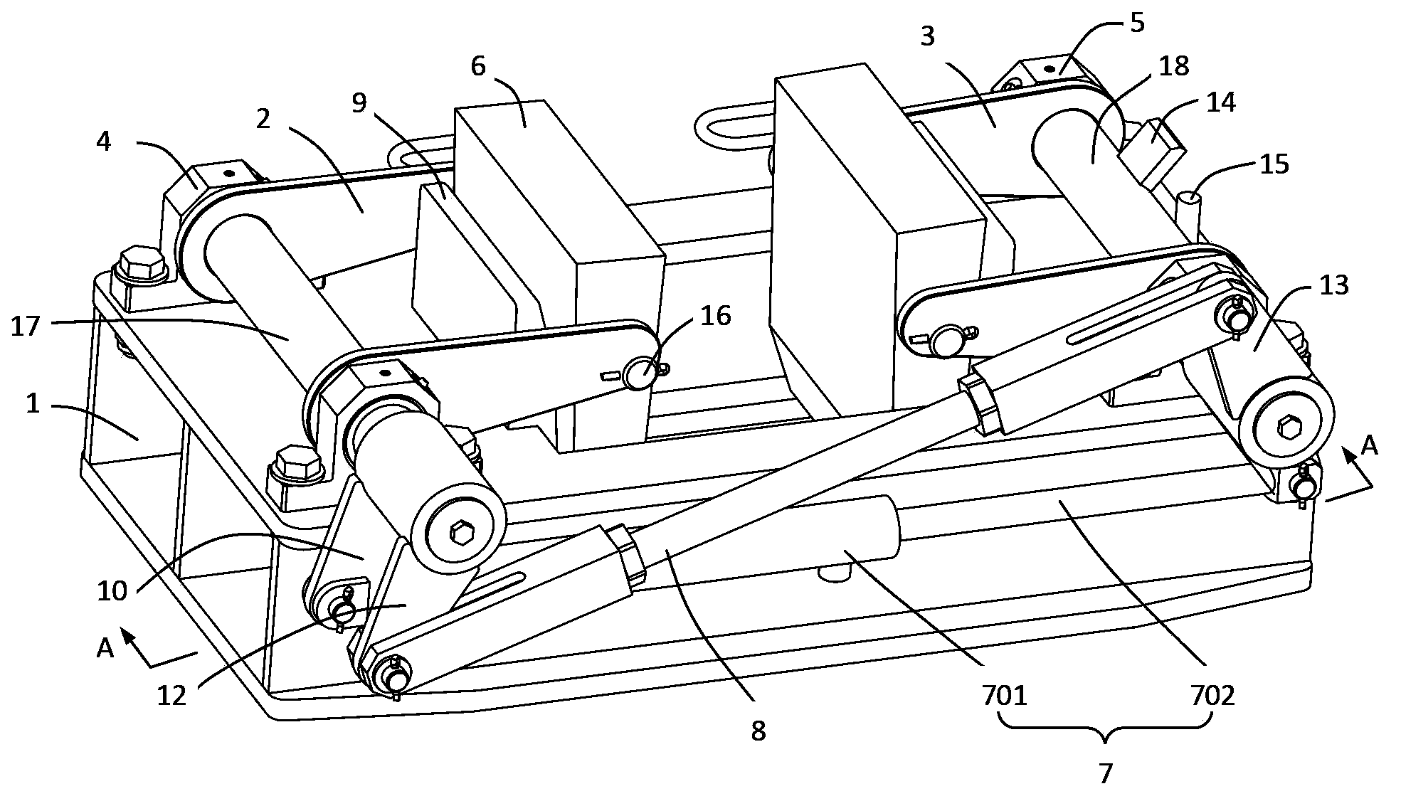
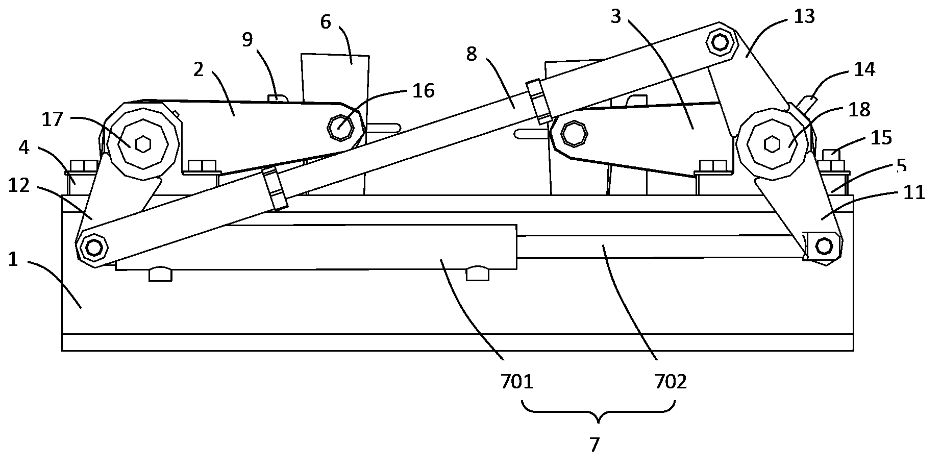
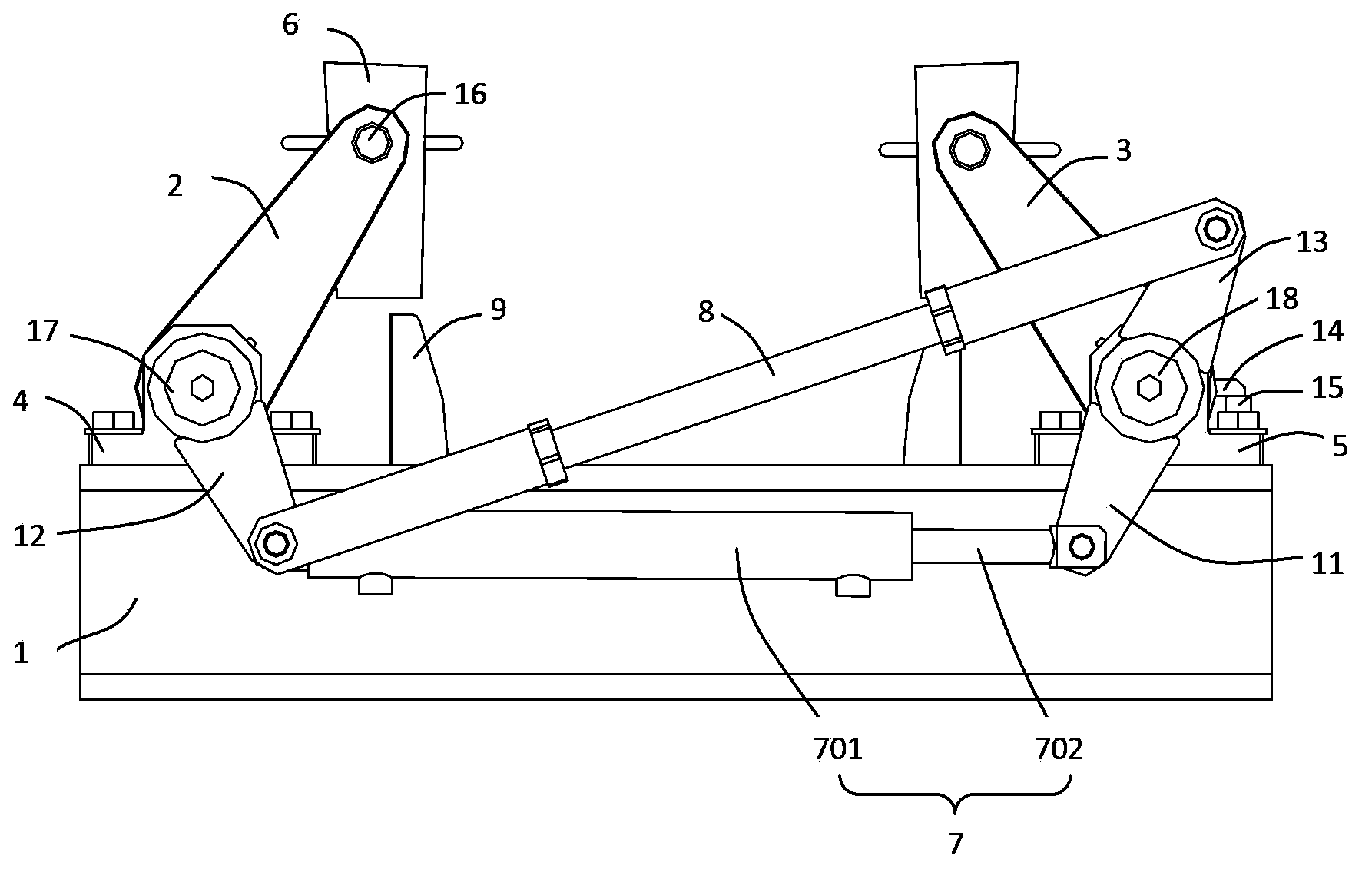
[0016] Such as Figure 1~4 As shown, the core drilling rig holder of the present invention includes a base 1, a left rotating shaft 17, a right rotating shaft 18, a left arm 2 and a right arm 3, and the left rotating shaft 17 and the right rotating shaft 18 pass through a pair of bearings respectively 4 and 5 are installed on the base 1, and one end of the left arm 2 and the right arm 3 is installed on the left shaft 17 and the right shaft 18 respectively, and the left shaft 17 and the right shaft 18 can be mounted on the left bearing 4 and the right side bearing 5 to rotate, thereby driving the left arm 2 and the right arm 3 to rotate, and the other ends of the left arm 2 and the right arm 3 are respectively hinged with the slips 6 for clamping the drill rod. exist Figure 1~4 In the illustrated embodiment of the core drilling rig holder of the present invention, the slip 6 is a two-piece slip, and the two parts are hinged to the left arm 2 and the right arm 3 respectively. ...


PUM


Abstract

The invention discloses a rock-core drill holder which comprises a base, a left-side rotating shaft, a right-side rotating shaft, a left arm and a right arm. Each of the left-side rotating shaft and the right-side rotating shaft is mounted on the base through a pair of bearings, and one ends of the left arm and the right arm are mounted on the left-side rotating shaft and the right-side rotating shaft respectively while the other ends of the same are hinged to a clamping tile used for clamping a drilling rod; the left-side rotating shaft or the right-side rotating shaft is driven to rotate through a hydraulic oil cylinder, and a connecting rod used for enabling the left-side rotating shaft and the right-side rotating shaft to synchronously and rotate in different directions is arranged between the left-side rotating shaft and the right-side rotating shaft. According to the rock-core drill holder, the clamping tile is reliable in clamping, so that safety in use of the rock-core drill holder is guaranteed.

Description

technical field [0001] The invention relates to a hydraulic rock core drilling equipment, in particular to a core drill holder. Background technique [0002] The gripper is a part of the hydraulic core drilling rig for loading and unloading the drill pipe. It is characterized by high operating frequency, reliable clamping and convenient operation. Most of the grippers used on hydraulic core drilling rigs are hydraulic elastic grippers or normally closed grippers. Holder. [0003] For the hydraulic elastic clamp, the clamping and loosening of the slips are realized by hydraulic pressure. When the oil inlets of the hydraulic cylinders on both sides are respectively supplied with high-pressure oil, the slips follow the movement of the piston and move closer to the center to clamp the drilling tool; change The high-pressure oil enters, and the slips deviate from the center to loosen the drilling tool. This type of holder has a relatively simple structure, but the clamping forc...

Claims


Application Information

Patent Timeline
Patent Type & Authority Applications(China)
IPC IPC(8): E21B19/16
Inventor 史俊龙杨敏耿现波
Owner ATLAS COPCO (NANJING) CONSTR & MINING EQUIP CO LTD
Why Eureka
Try Eureka