Analytical equipment of frequency conversion electricity based on digital transmission

An analysis device and digital quantity technology, applied in the field of instruments, can solve the problems of low accuracy, many error links, and short paths, etc., and achieve the effect of increasing the number of analysis times, improving accuracy, and improving precision

Inactive Publication Date: 2014-10-22
徐伟专
View PDF4 Cites 3 Cited by
  • Summary
  • Abstract
  • Description
  • Claims
  • Application Information

AI Technical Summary

Problems solved by technology

[0004] From a theoretical analysis, the existing frequency conversion instrument can adopt the following methods: see the attached figure 1 , part 1-2 of this structure is a whole, and part 1-2 is usually used as an independent instrument, and the digital transmission system is often realized by PCB, and the path is very short; part 1-1 and part 1-2 together constitute the analyzer system, The analog quantity transmission link between part 1-1 and part 1-2 uses cables, and the length of the cable is determined according to the needs of the test site, which is a link that is easy to introduce loss and interference; the structural part 1-1, part 1-2 and the analog Errors may be introduced in the quantity transmission link (mainly electromagnetic interference and signal attenuation and other factors), and the accuracy is not high; the system accuracy is determined by the voltage sensor, current sensor, transmission part, and secondary transmitter part, and many error links are introduced. Most of the equipment is suitable for the power frequency environment and is not suitable for the measurement of variable frequency power

Method used


Image

  • Analytical equipment of frequency conversion electricity based on digital transmission
  • Analytical equipment of frequency conversion electricity based on digital transmission
  • Analytical equipment of frequency conversion electricity based on digital transmission

Examples


Embodiment 1

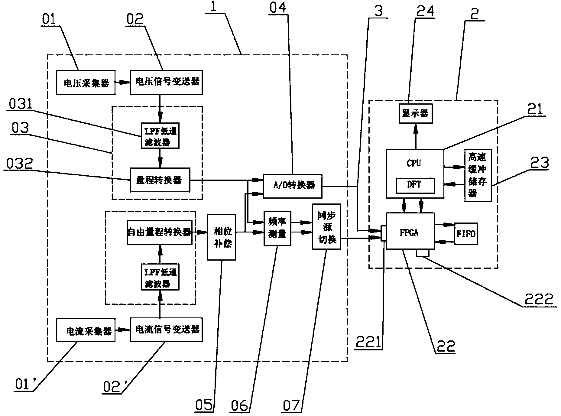
[0034] An analysis device for variable frequency electricity based on digital quantity transmission, see figure 2 , including a power unit 1, an analyzer 2, and a communication unit 3. The power unit 1 is a built-in PCB board with a built-in structure, which can not only prolong its service life, but also reduce the overall volume of the device, which greatly saves space. And the interference of the external environment is reduced, and the overall structure is simplified.

[0035]The power unit 1 includes two parallel power unit units, and one power unit unit includes a voltage collector 01, a voltage signal transmitter 02, a signal conditioning component 03, an A / D converter 04 and A frequency measurement component 06 and a synchronous source switching component 07 connected in series and in parallel with the A / D converter 04; the other power unit unit includes a current collector 01', a current signal transmitter 02', The signal conditioning component 03, the phase compens...


PUM


Abstract

The invention provides analytical equipment of frequency conversion electricity based on digital transmission. The analytical equipment contains a power unit, an analyzer and a communication unit. The power unit contains at least a power unit singleton which comprises a sampling part, a signal transformer, a signal conditioning part and an A/D converter which are successively connected in series. The analyzer contains a CPU module, an editable logic device, a high-speed buffer memory and a display screen. The CUP module is respectively connected with the display screen, the editable logic device and the high-speed buffer memory. A Discrete Fourier Transform (DFT) algorithm is arranged inside the CUP module. The editable logic device is connected with the A/D converter through the communication unit. The whole structure of the analytical equipment is simplified. As the power unit converts analog quantity to a digital signal for transmission, influence of transmission distance and electromagnetic environment is avoided, and precision of a system is raised. By integrating the CPU module, the editable logic device and the high-speed buffer memory, arithmetic speed and handling capacity are raised of the analytical equipment are raised, and the analytical equipment has high practicality.

Description

technical field [0001] The invention relates to the field of instruments, in particular to an analysis device for variable frequency electricity based on digital quantity transmission. Background technique [0002] The traditional power analyzer adopts the following method: the front-end sensor converts the voltage and current into a small signal (analog signal) acceptable to the secondary instrument, and the analog signal is transmitted to the secondary instrument through the cable for ratio conversion and display. So how to measure the measurement accuracy of the whole measurement system? According to the composition of the measurement system, the measurement accuracy of the system should be determined by the following three aspects: 1. The accuracy of the front-end sensor; 2. The interference and signal attenuation introduced by the transmission line; 3. The measurement accuracy of the secondary instrument. The sensor of this technology is connected with the secondary ca...

Claims


Application Information

Patent Timeline
Patent Type & Authority Applications(China)
IPC IPC(8): G01R21/133G01R31/00
Inventor 徐伟专廖仲篪庞林
Owner 徐伟专
Why Eureka
Try Eureka