A fiber optic connector

An optical fiber connector and back cover technology, which is applied in the field of optical fiber connectors, can solve the problems of low assembly efficiency, broken wire cores, and the fiber core is inserted into the rear end surface of the flange, so as to achieve the effect of improving the success rate of assembly.

Inactive Publication Date: 2016-09-21
CHINA AVIATION OPTICAL-ELECTRICAL TECH CO LTD
View PDF6 Cites 1 Cited by
  • Summary
  • Abstract
  • Description
  • Claims
  • Application Information

AI Technical Summary

Problems solved by technology

Due to the low efficiency of manual assembly, it is currently trying to use automated assembly equipment to produce optical fiber connectors. However, the steps of automated assembly are: first assemble the ferrule, flange, spring 8, front sleeve, and rear sleeve, etc., and then Carry out the steps of glue injection, fiber stripping, fiber threading and subsequent grinding, because the parts are assembled first and then glue injection and fiber threading are performed. The flange is far away from the rear end of the back sleeve, and the glue injection machine head is very easy to inject during glue injection. It is blocked by the rear end face of the flange and cannot be inserted into the flange, and finally the assembly fails due to the glue overflowing the flange; in addition, it is very easy for the fiber core 7 to enter between the flange and the back sleeve Radial gap, or the core is inserted into the rear end face of the flange and the core is broken, which eventually leads to assembly failure

Method used


Image

  • A fiber optic connector
  • A fiber optic connector
  • A fiber optic connector

Examples


Embodiment Construction

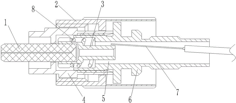
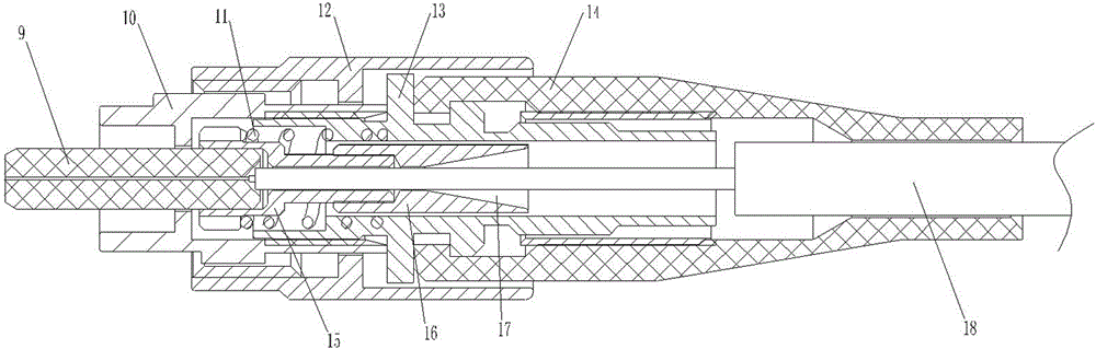
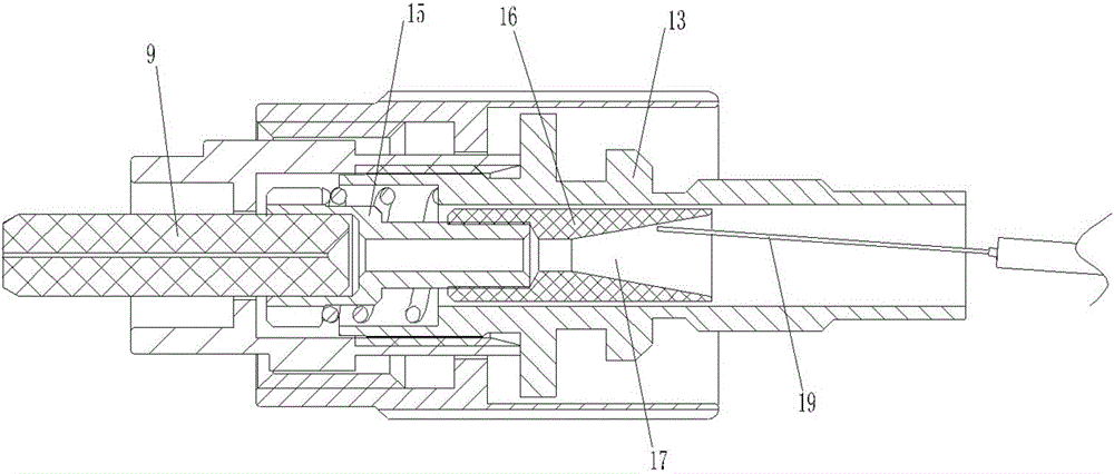
[0016] Examples of fiber optic connectors are Figure 2~3 Shown: including the front cover 10, the rear cover 13 and the flange 15 with the ferrule 9 at the front end, the front cover is screwed with the connecting nut 12, and the rear end of the flange extends into the inner hole of the rear cover. There is a radial gap between the rear end of the flange and the wall of the inner hole of the rear sleeve. The rear end of the flange is screwed with a guide structure 16. The outer end of the guide structure is located in the radial gap, and the guide structure extends into the In the inner hole of the rear sleeve, the guide structure is matched with the inner hole wall of the rear sleeve at the same time, so that the guide structure can move back and forth in the inner hole of the rear sleeve without affecting the axial movement of the flange when the connector is docked. The guide structure is provided with a guide hole 17 in which the front end communicates with the inner hole...


PUM


Abstract

The invention relates to an optical fiber connector. The optical fiber connector comprises a flange plate and a back sleeve, a guide structure is arranged on the flange plate or the back sleeve, a guide hole is formed in the guide structure, the front end of the guide hole is communicated with an inner hole of the flange plate, the rear end of the guide hole is communicated with an inner hole of the back sleeve, and the guide hole is in a taper shape with the aperture which is gradually reduced from the rear to the front. The guide structure is arranged on the flange plate or the back sleeve so that when glue injection or fiber penetration is performed, a gluing machine needle head or a wire core penetrates from the rear end of the back sleeve, the gluing machine needle head or the wire core can be gradually guided into the inner hole of the flange plate along the tapered hole walls of the guide hole, the gluing machine needle head and a fiber core can be easily inserted into the inner hole of the flange plate, and the assembly success rate of the optical fiber connector is increased.

Description

technical field [0001] The present invention relates to optical fiber connectors for optical signal transmission. Background technique [0002] The structure of existing FC, SC and other optical fiber connectors is as follows: figure 1 Shown: It includes a housing with the front end as the plug-in end, the housing includes a front sleeve 4 and a rear sleeve 6 assembled together, a connecting nut 2 rotates on the housing, and a flange with a ferrule 1 is arranged in the housing 3. The rear end of the flange extends into the inner hole of the rear sleeve. In order to ensure the axial movement of the flange when the connector is docked, there is a radial gap between the flange and the inner hole wall of the rear sleeve 5 . In the past, fiber optic connectors were manually assembled, and the optical fiber was manually inserted into the inner hole of the flange from back to front, and then the flange was assembled into the housing. Due to the low efficiency of manual assembly,...

Claims


Application Information

Patent Timeline
Patent Type & Authority Patents(China)
IPC IPC(8): G02B6/38
Inventor 王琦
Owner CHINA AVIATION OPTICAL-ELECTRICAL TECH CO LTD
Why Eureka
Try Eureka