Reference circuit capable of being calibrated and used for UHF RFID label chip

A technology for calibrating benchmarks and tag chips, applied in the direction of adjusting electrical variables, control/regulating systems, instruments, etc., can solve problems such as the prominent effect of MOS tubes and the deviation of the output voltage of the reference source from the design value.

Active Publication Date: 2014-10-22
NAT UNIV OF DEFENSE TECH +1
View PDF5 Cites 11 Cited by
  • Summary
  • Abstract
  • Description
  • Claims
  • Application Information

AI Technical Summary

Problems solved by technology

However, due to the smaller and smaller process size at this stage, various advanced effects of MOS tubes are highlighted. In this way, not only human factors in the design process or human errors in the drawing process, but also systematic errors in the manufacturing process will eventually Cause the output voltage of the reference source to deviate from the original design value

Method used


Image

  • Reference circuit capable of being calibrated and used for UHF RFID label chip
  • Reference circuit capable of being calibrated and used for UHF RFID label chip
  • Reference circuit capable of being calibrated and used for UHF RFID label chip

Examples


Embodiment Construction

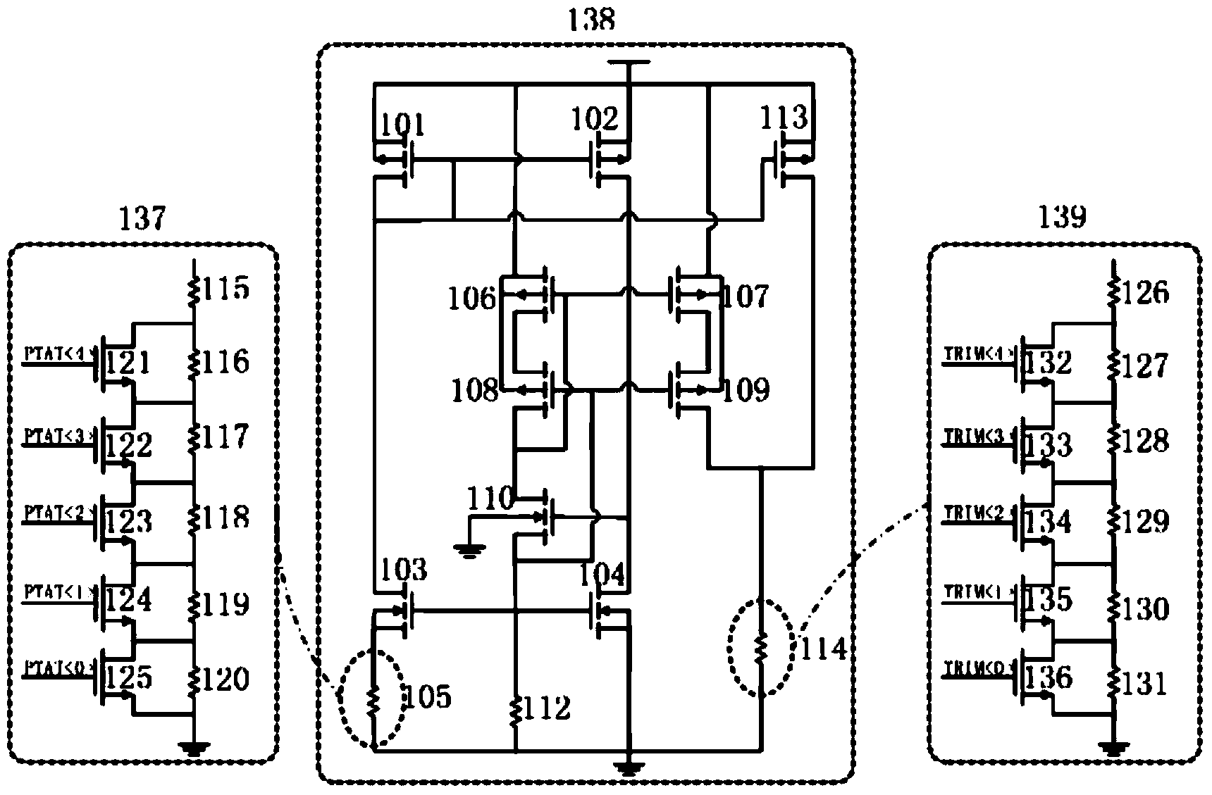
[0034] refer to figure 1 , a calibrated reference circuit for a passive UHF RFID tag chip according to the present invention mainly includes three parts, which are a standard reference circuit 128, a positive temperature coefficient current calibration circuit 127, and a reference voltage output calibration circuit 129. Wherein, the standard reference circuit 128 is a core circuit, and it includes three main parts, which are respectively a positive temperature coefficient current generating circuit (i.e. a PTAT circuit), consisting of two PMOS transistors, that is, a first PMOS transistor 101 and a second PMOS transistor 102, Two NMOS tubes, namely the first NMOS tube 103 and the second NMOS tube 104, are composed of a first resistor 105 with a very low temperature coefficient, and its temperature coefficient is only -9.2X10 -4 ppm / °C. The gate of the first PMOS transistor 101 is connected to the gate of the second PMOS transistor 102 and at the same time connected to its own...


PUM


Abstract

The invention discloses a reference circuit capable of being calibrated and used for a UHF RFID label chip. The reference circuit capable of being calibrated and used for the UHF RFID label chip comprises a standard reference circuit, a PTC (positive temperature coefficient) current calibration circuit and a reference voltage output calibration circuit, wherein the standard reference circuit comprises a PTC electric current generation circuit, an NTC (negative temperature coefficient) current generation circuit and a reference voltage output circuit, and a reference output voltage with the smallest deviation value is obtained by configuring a calibration code. The reference circuit capable of being calibrated and used for the UHF RFID label chip overcomes potential personal error and systematic deviation during the design process, obtains a relatively stable reference voltage value after being calibrated, provides guarantees for subsequently obtaining a stable clock and stable work of a digital module, and improves efficiency of the label chip. The reference circuit capable of being calibrated and used for the UHF RFID label chip achieves a relatively simple mechanism, and completes calibration work under the circumstance of not increasing power consumption.

Description

technical field [0001] The invention relates to the field of analog integrated circuits, in particular to a design of a calibrated reference circuit for a passive ultra-high frequency radio frequency identification tag chip. Background technique [0002] With the rise of Internet of Things technology, Radio Frequency Identification (RFID) technology is also developing rapidly. Among them, UHF passive tag chips are becoming more and more popular in the market due to their advantages of high accuracy, large storage capacity, reusability, non-contact reading and writing, strong security, and the ability to identify multiple objects at the same time. [0003] Passive radio frequency identification (RFID) system is mainly composed of three parts: card reader, antenna and tag chip. The tag chip mainly includes four main modules: analog (radio frequency) front-end circuit, digital baseband, some control modules and non-volatile memory. Among them, the reference circuit belongs to...

Claims


Application Information

Patent Timeline
Patent Type & Authority Applications(China)
IPC IPC(8): G05F1/56
Inventor 李建成郑礼辉蔡磊郭俊平李松亭谷晓忱郑黎明曾祥华李浩
Owner NAT UNIV OF DEFENSE TECH
Why Eureka
Try Eureka