
A Multi-mode Programmable Frequency Divider

A technology of frequency divider and frequency division ratio, which is applied in the direction of pulse counter, counting chain pulse counter, pulse technology, etc., can solve the problem of waste of power consumption, and achieve the effect of avoiding waste of power consumption

Active Publication Date: 2018-09-28
SANECHIPS TECH CO LTD
View PDF3 Cites 0 Cited by
  • Summary
  • Abstract
  • Description
  • Claims
  • Application Information

AI Technical Summary

Problems solved by technology

[0006] In view of this, the main purpose of the present invention is to provide a multi-mode programmable frequency divider, to solve the waste of power consumption of the existing multi-mode programmable frequency divider

Method used


Image

  • A Multi-mode Programmable Frequency Divider
  • A Multi-mode Programmable Frequency Divider
  • A Multi-mode Programmable Frequency Divider

Examples


Embodiment Construction

[0025] The technical solutions of the present invention will be further elaborated below in conjunction with the accompanying drawings and specific embodiments.

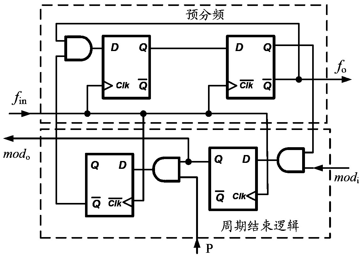
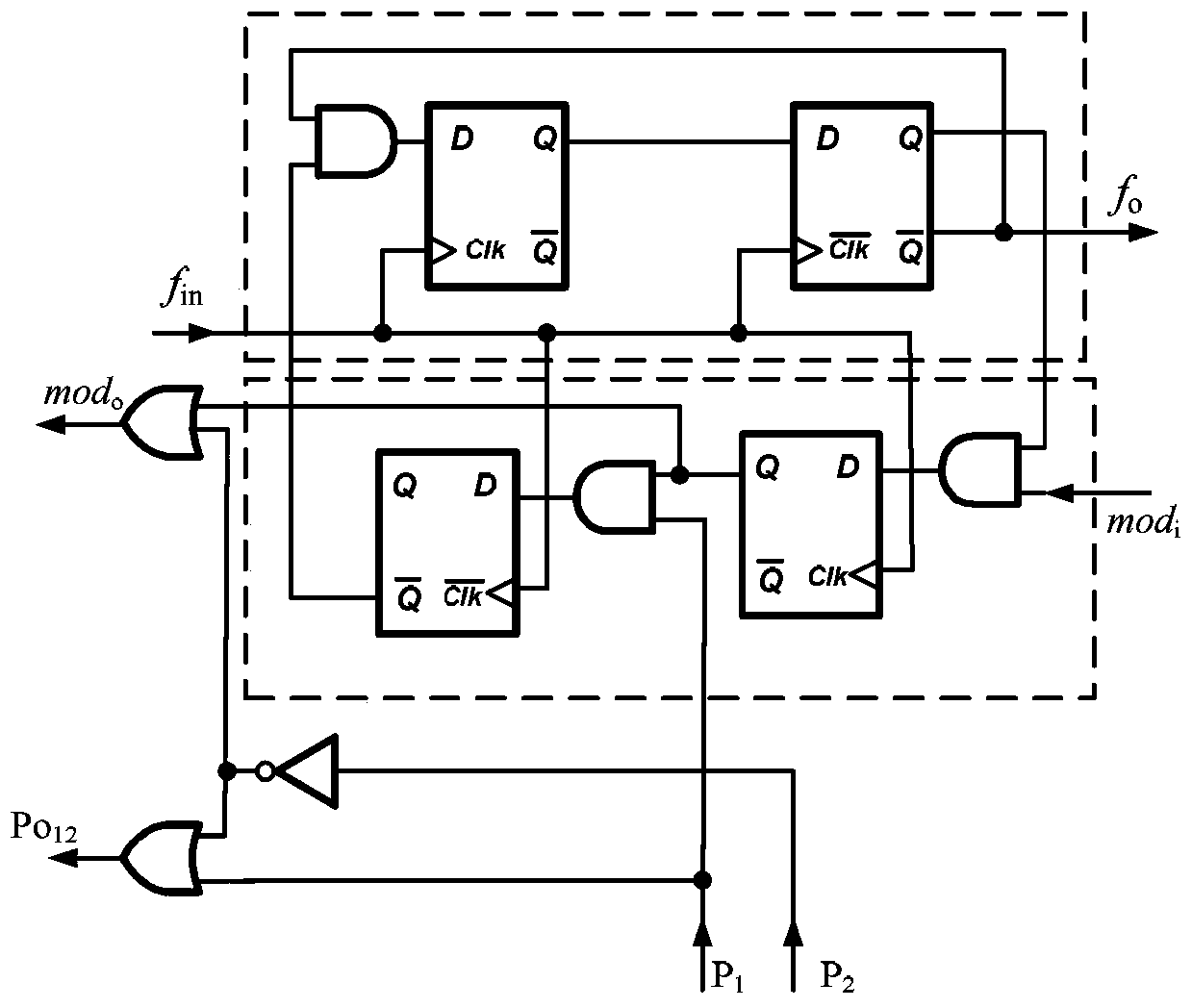
[0026] A multi-mode programmable frequency divider provided by an embodiment of the present invention, such as Figure 4 As shown, it includes: the main frequency division stage composed of cascaded 2 / 3 frequency division units, the number of 2 / 3 frequency division units without frequency division ratio extension bits in the cascaded 2 / 3 frequency division units For Ne, the quantity of the 2 / 3 frequency division unit with frequency division ratio expansion bit is n-Ne, and Ne is the effective number of digits of the multimode programmable frequency divider; The 2 / 3 frequency division unit of the cascade The total number n is determined according to the required maximum frequency division ratio, which is 2 n+1 -1, the minimum frequency division ratio of the multimode programmable frequency divider is determined accor...


PUM


Abstract

Disclosed is a multimode programmable frequency divider, comprising: cascaded 2 / 3 frequency dividing units, a real-time power consumption control circuit, and a power switch control transistor, wherein the number of the frequency dividing units without a frequency dividing ratio extension bit and the number of the frequency dividing units with the extension digit are Ne and n-Ne, respectively; the real-time power consumption control circuit is composed of n-Ne-1 levels of two-input AND gates; the reverse signal of the frequency dividing ratio control bit of the n-th level of the frequency dividing unit is connected to the power control bit of the n-th level of the frequency dividing unit; the reverse signal, and the reverse signal of the frequency dividing ratio control bit of the (n-1)-th level of the frequency dividing unit are connected to the input end of the n-th level of the AND gate; the output end of the n-th level of the AND gate is connected to the power control bit of the (n-1)-th level of the frequency dividing unit, and the reverse signal of the frequency dividing ratio control bit of the (n-2)-th level of the frequency dividing unit is correspondingly connected to the input end of the (n-1)-th level of the AND gate; the subsequent connections are completed in a similar way until the reverse signal of the frequency dividing ratio control bit of the (n-Ne)-th level of the frequency dividing unit is connected to the input end of the (n-Ne-1)-th level of the AND gate; the drain of the power switch control transistor is connected to the power ends of the frequency dividing units with the extension bit, the source of the power switch control transistor is connected to a power supply, and the grid of the power switch control transistor is connected to the power control bits of the frequency dividing units with the extension bit.

Description

technical field [0001] The invention relates to the field of frequency divider design, in particular to a multi-mode programmable frequency divider. Background technique [0002] In order to improve the spectrum utilization rate of the system, most mobile communication systems adopt frequency division multiplexing technology, and the channel of the transceiver will be switched in real time according to the channel occupancy and channel quality when the transceiver communicates. The frequency synthesizer provides the carrier signal for the transceiver, and the programmable frequency divider is the core device in the frequency synthesizer, which directly controls the channel selection and is the key to the entire tunable chip design. Therefore, high operating frequency, wide frequency division ratio range, low power consumption, etc. are usually the general requirements of the system for frequency dividers. [0003] The multi-mode programmable frequency divider is a programma...

Claims


Application Information

Patent Timeline
Patent Type & Authority Patents(China)
IPC IPC(8): H03K23/66
CPCH03K23/667H03K19/17784
Inventor 易律凡彭关超刘永才谢豪律周栋梁
Owner SANECHIPS TECH CO LTD
Learn More