
Frame used for combining plurality of motors

A rack and meshing technology, which is applied in the field of racks for combining multiple motors, can solve the problems of easy wear of key moving parts, high motor heat generation, and high power consumption, so as to reduce harmful mechanical wear noise and stabilize the structure Compact and durable, the effect of increasing the service life

Inactive Publication Date: 2015-11-25
万伟
View PDF0 Cites 6 Cited by
  • Summary
  • Abstract
  • Description
  • Claims
  • Application Information

AI Technical Summary

Problems solved by technology

[0003] In order to overcome the shortcomings of the traditional electric fan, such as large heat generation, easy wear of key moving parts, and high power consumption, the invention provides a frame for combining multiple motors. The frame combines multiple motors (low power) Combined into a high-power (relative to the output power of a single motor) motor combined power source, the power output of multiple motors combined through the rack has high energy efficiency and low heat generation, and is suitable for driving a variety of electrical equipment, and the working voltage can be as low as Below the safe voltage, compared with the power structure of traditional electrical equipment driven by one motor, its weight is lighter and its structure is stronger, especially the power output shaft of the combined power source of multiple motors combined in this rack is more durable and not easy to wear

Method used


Image

  • Frame used for combining plurality of motors
  • Frame used for combining plurality of motors
  • Frame used for combining plurality of motors

Examples


Embodiment Construction

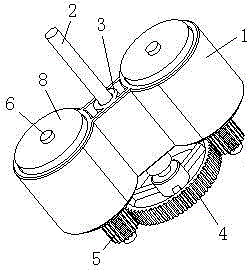
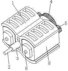
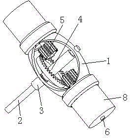
[0035] Such as figure 1 Among them, a frame for combining multiple motors includes a transmission shaft 2, a center wheel 4 fixed on the transmission shaft 2, and a nesting body 1 sleeved on the transmission shaft 2, and the center line of the center wheel 4 is aligned with the transmission shaft. Axis 2 center lines coincide;

[0036] The nesting body 1 includes two fixing grooves 7 and fixing parts connecting the fixing grooves 7. The two fixing grooves 7 are symmetrically arranged with the transmission shaft 2 as the axis of symmetry. The power output shaft 6 of the motor 8 in the groove 7 is provided with a gear 5, and the edge of the center wheel 4 is provided with teeth, and the teeth of the center wheel 4 are meshed with the gear teeth 5 on the power output shaft 6 (or as Image 6 Among them, the power output shaft 6 of the motor 8 placed in the fixed groove 7 is provided with a power split pulley 12, and the power split pulley 12 is connected with the center wheel 4 t...


PUM


Abstract

Provided is a frame used for combining a plurality of motors, comprising a transmission shaft, one or more than one center wheel fixed to the transmission shaft, and a nested body sleeving the transmission shaft. The center line of the center wheel is superposed on the center line of the transmission shaft; the nested body comprises a plurality of fixing slots, and fixing members for connecting the fixing slots, wherein the fixing members are in movable connection with the transmission shaft, and are arranged in the fixing slots; motor power output shafts and the center wheel are in mechanical connection; the nested body integrates the transmission shaft and motors respectively arranged in the fixing slots into a stress whole body with a stable structure. In operation, a plurality of motors provide torque force for the center wheel in a same direction to drive the transmission shaft to rotate. A plurality of motors combined through the frame have the characteristics of high energy efficiency and low heating, are suitable for driving a plurality of kinds of electric appliances, and have a work voltage lower than a safety voltage; compared with a traditional one motor-driven power structure, the plurality of motors combined through the frame are firmer, and the power output shafts of the combined power sources of the plurality of motors combined through the frame are more durable.

Description

technical field [0001] The invention relates to a frame capable of fixing multiple motors to output power coaxially. The multiple motors fixed by the frame are especially suitable for driving household electric fans, industrial ventilating fans, cooling fans, etc., which require less power output. device. Background technique [0002] The power of small driving motors commonly used in daily life and production generally does not exceed 300 watts, and they can all be driven by one motor. Taking the structure of a household electric fan as an example, the fan blades are directly connected to the motor rotor coaxially. The advantage is that the structure is simple and easy to assemble and produce. However, this structure causes a large load on the motor rotor, resulting in high heat generation inside the motor; and the motor rotor and the front and rear bearings of the motor are easily worn due to the rotation of the fan blades, etc. After the wear, the motor load increases ag...

Claims


Application Information

Patent Timeline
IPC IPC(8): H02K51/00H02K5/00
Inventor 万伟
Owner 万伟
Learn More