System and method for solar energy utilization

A technology of solar energy and solar concentrators, applied in the field of solar energy utilization systems, can solve problems such as not very economical

Inactive Publication Date: 2014-10-22
OR HAMA ENERGY
View PDF10 Cites 27 Cited by
  • Summary
  • Abstract
  • Description
  • Claims
  • Application Information

AI Technical Summary

Problems solved by technology

Therefore, solar energy systems, despite their green advantages, are not very economical compared to conventional energy sources

Method used


Image

  • System and method for solar energy utilization
  • System and method for solar energy utilization
  • System and method for solar energy utilization

Examples


Embodiment approach

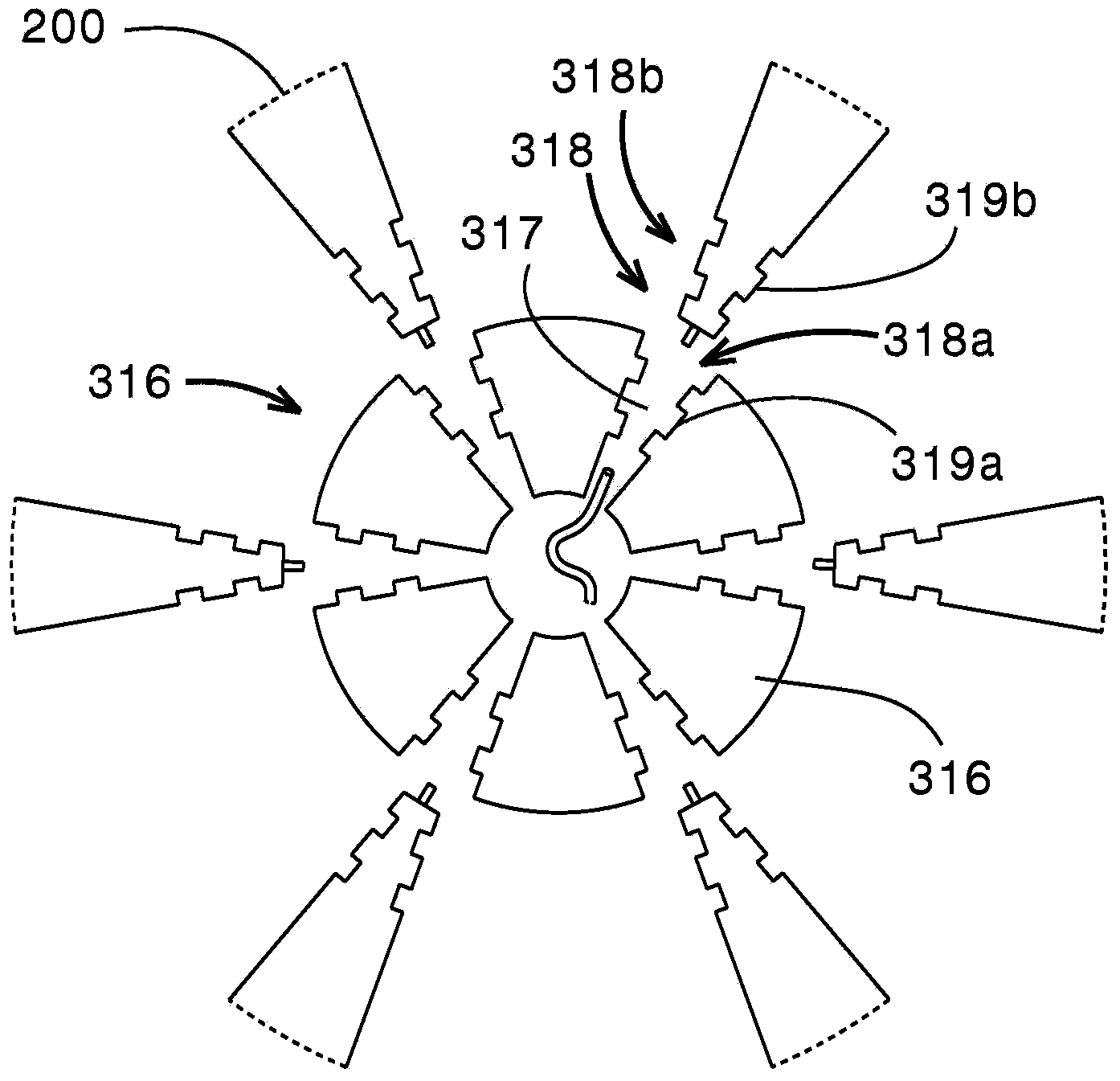
[0134] According to one embodiment, each concave portion 318a of the blade locking mechanism 318 comprises a corresponding slot 317 arranged in the body of the retaining disc 316 . Such as Figure 1C As shown, the inner surface of the slot 317 is not uniform, but instead includes one or more tooth-shaped slot irregularities 319a. On the other hand, each flexible mirror 200 includes a corresponding blade irregularity 319b having a shape adapted to match the slot irregularity 319a.

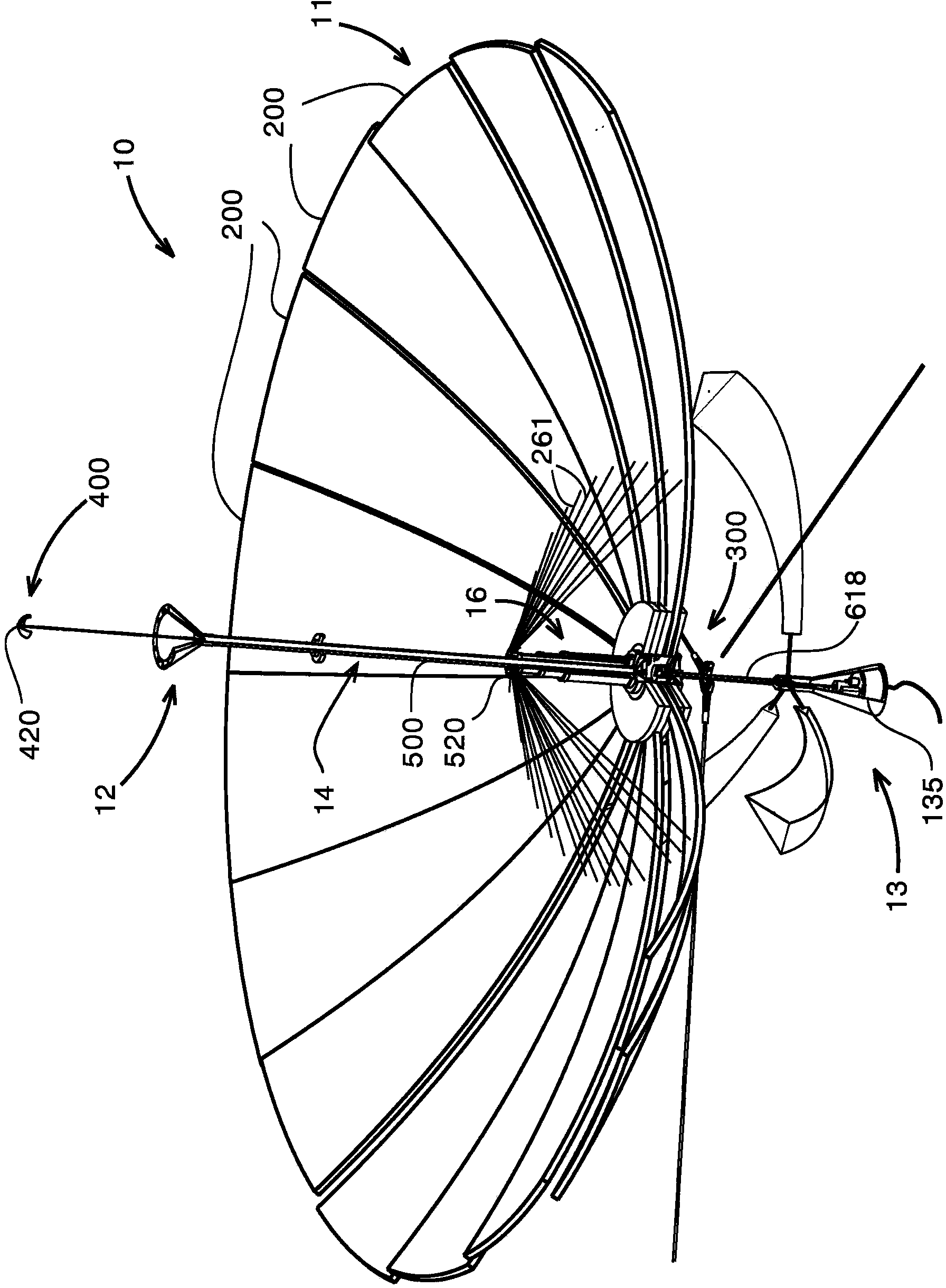
[0135] The flexible mirror 200 can be folded at any time. Therefore the surface of the solar receiver can be retracted. By folding, the mirror 200 changes shape to a compact shape with a lower aerodynamic profile, which can provide protection against harsh external factors such as strong winds, debris, insects, dust, dirt, rain, dew, snow and other Protection from adverse weather conditions that may affect the system during development).

[0136] back to Figure 1A , in order to fold up the flex...


PUM


Abstract

A system for solar energy utilization is described. The system comprises a solar receiver, a solar energy concentrator mounted on a pole extending from the solar receiver along the main axis of the system, and a solar tracking system. The solar receiver is configured for receiving solar energy from the sun and concentrating the received solar energy at a predetermined spot area. The solar receiver includes a plurality of flexible mirrors independent of each other and radially arranged around a main axis of the system. The flexible mirrors are configured to be either deployed for operation or collapsed, for example for transportation or in the cases of possible damage of the system. The solar energy concentrator is located at the predetermined spot area in which the solar energy reflected from said plurality of flexible mirrors is concentrated, and configured for converting the concentrated reflected energy into electric energy. The solar tracking system is configured for sensing position of the sun and tilting the system for directing the solar receiver towards the sun to receive and reflect maximum sunlight onto the predetermined spot area.

Description

technical field [0001] The present invention relates generally to a system and method for solar energy utilization, and more particularly to a dynamic method and apparatus for generating electricity. Background technique [0002] There are two main types of solar energy systems to date, namely: (a) a thermal system based on mirrors that concentrate sunlight and generate energy through heat. This thermal system is mirror based and efficient, but it is generally too costly; and (b) a photovoltaic (PV) system comprising photovoltaic cells that convert incident energy into electrical energy. [0003] For example, U.S. Patent Application No. 2012 / 0118351 describes a solar generator comprising an array of photovoltaic elements and a single continuous smooth solar reflective surface arranged to reflect light from the sun to the array of photovoltaic power generation elements. [0004] US Patent Application No. 2011 / 0265852 describes an open concentrating system for solar radiatio...

Claims


Application Information

Patent Timeline
Patent Type & Authority Applications(China)
IPC IPC(8): F24J1/00B64G1/44H01Q15/14F24S20/20F24S23/70F24S23/71F24S50/20F24V30/00
CPCY02E10/52H01L31/0525Y02E10/47F24J2/36H01Q15/162H01Q15/14Y02E10/42F24J2/4607F24J2/1057F24J2002/1085F24J2/125F24J2002/5482F24J2/07F24J2/5431B64G1/44F24J2/4638F24J2002/5441H01L31/0547H04W8/04H04W60/00H04W88/14H02S20/32F24S40/85F24S30/48F24S20/50F24S40/00F24S2023/874F24S20/20F24S2030/115F24S2030/15F24S23/715F24S23/82H02S20/30H04W48/18F24S20/55Y02E10/40
Inventor G·布劳
Owner OR HAMA ENERGY
Why Eureka
Try Eureka