Compensator system and method for compensating angular dispersion

A compensator and angular dispersion technology, applied in the field of compensator systems, can solve the problem that a single prism is not enough to compensate angular dispersion

Active Publication Date: 2014-10-22
FEMTONICS
View PDF6 Cites 11 Cited by
  • Summary
  • Abstract
  • Description
  • Claims
  • Application Information

AI Technical Summary

Problems solved by technology

In practice, however, angular dispersion depends on the applied acoustic frequency, so a single prism is not sufficient to compensate for angular dispersion at all frequencies

Method used


Image

  • Compensator system and method for compensating angular dispersion
  • Compensator system and method for compensating angular dispersion
  • Compensator system and method for compensating angular dispersion

Examples


Embodiment Construction

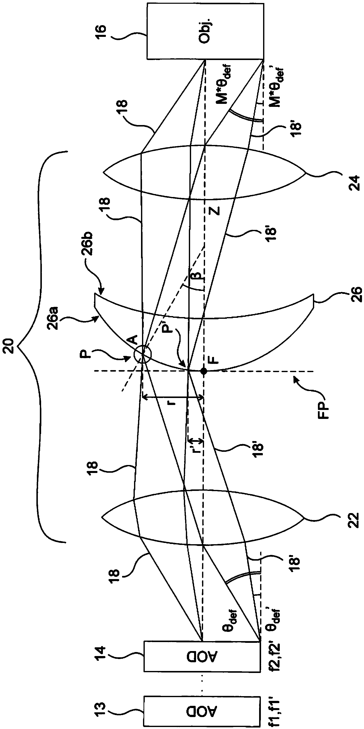
[0026] figure 2 A compensator system 20 according to the invention is shown arranged between a second AOD 14 of a pair of consecutive AODs 13, 14 and an objective lens 16 of an optical system such as a laser scanning microscope (not shown). The optical system may include individual optical elements between two consecutive AODs 13, 14, as discussed in WO2010 / 076579, and additionally, the optical system typically includes a second pair of AODs such that the first pair of AODs is used in the first lateral direction The electromagnetic beam 18 is deflected in x, while the second pair of AODs deflects the beam 18 in a second transverse direction y, perpendicular to the first transverse direction x. For simplicity, only one consecutive pair of AODs 13 and 14 is shown and discussed in the following, however, in the transverse direction corresponding to the second pair of AODs, the beam deflection can be calculated similarly.

[0027] The compensator system 20 includes a first lens ...


PUM


Abstract

The invention relates to a compensator system adapted to compensate for the angular dispersion of electromagnetic beams deflected by at least one acousto-optic deflector of an optical system, wherein the angular dispersion of each deflected beam is dependent on the deflection angle obtained by the deflecting acoustic frequency of the acousto-optic deflector, characterised in that the compensator system comprises: - a first lens group for spatially separating the deflected beams of different deflection angle and angular dispersion by focusing the beams substantially into the focal plane, - a compensator element having a first surface and a second surface, and being arranged such that the first surface of the compensator element lies substantially in the focal plane of the first lens group, and the first and second surfaces of the compensator element have nominal radiuses R1 and R2 that together work as prisms with tilt angles beta and prism opening angles alphap that vary with the distance from the optical axis so as to compensate for the angular dispersion of the spatially separated deflected beams, - a second lens group arranged so as to substantially parallelise the different wavelength components of each deflected beam exiting the compensator element while maintaining the angular variation of the beams deflected at different acoustic frequencies. The invention further relates to method for compensating for the angular dispersion of electromagnetic beams deflected by at least one acousto-optic deflector of an optical system, wherein the angular dispersion of each deflected beam is dependent on the deflection angle obtained by the deflecting acoustic frequency, characterised by - spatially separating the deflected beams of different deflection angle and angular dispersion by focusing the beams via a first lens group substantially into the focal plane of the first lens group, - compensating for the angular dispersion of the spatially separated deflected beams in accordance with the angular dispersion of the given beam, - substantially parallelising the spectral components of each deflected beam while maintaining the angular variation of the beams deflected at different acoustic frequencies.

Description

technical field [0001] The present invention relates to a compensator system and method suitable for compensating the angular dispersion of electromagnetic beams deflected by at least one pair of acousto-optic deflectors of an optical system, wherein the angular dispersion of each deflected beam depends on the The deflection angle obtained by deflecting the audio frequency. Background technique [0002] Three-dimensional (3D) random access laser scanning technology is important in performing measurements (including scanning, imaging, detection, excitation, etc.) on biological specimens, such as imaging biological structures or determining fluorescent labeling of cell surface receptors or performing such Measurement of release / photosimulation, FRET (fluorescence resonance energy transfer), FLIM (fluorescence lifetime imaging), and the like. [0003] Commonly used 3D laser scanning microscopes are confocal microscopes or multiphoton (two-photon) microscopes. In confocal micr...

Claims


Application Information

Patent Timeline
Patent Type & Authority Applications(China)
IPC IPC(8): G02F1/33G02B21/00G02B27/00
CPCG02F1/33G02B21/002G02B27/0031G02B5/04G02B21/0036G02B27/30
Inventor B.罗兹萨G.卡托纳M.维雷斯P.马克G.扎莱
Owner FEMTONICS
Why Eureka
Try Eureka