
Intelligent upper limb auxiliary motion device

An exercise device and upper limb technology, applied in passive exercise equipment, physical therapy, etc., can solve problems such as limited movement direction and range of affected limbs, inability to lift shoulder joints outwards, secondary injuries, etc., and achieve fixation And the effects of easy disengagement, no risk of secondary injury, and smooth power transmission

Active Publication Date: 2014-10-29
蒋文庆
View PDF8 Cites 8 Cited by
  • Summary
  • Abstract
  • Description
  • Claims
  • Application Information

AI Technical Summary

Problems solved by technology

One disadvantage of this method is that patients need to be accompanied by other people to and from the rehabilitation center frequently, which brings great inconvenience to patients in places far away from the rehabilitation center.
The second is that the cost of rehabilitation is relatively expensive. Medical technicians are intermediate and senior technical personnel, and the rehabilitation process will take up more time for technicians. At the same time, rehabilitation often lasts for several years. This cost has brought troubles to many families.
Its shortcoming is that the direction and range of movement of the affected limb are very limited. The device can only be placed in front of the patient, and it can move up, down, back and forth within a limited range.
The disadvantages are that the cost is high, the patients still have to travel between home and the rehabilitation center, the third is that it can only perform actions according to the pre-programmed procedures, and the fourth is that the perception of pain is not timely enough under the existing technical conditions. , the fifth is how to eliminate the delay between pain perception and equipment stop working, and the resulting secondary injury

Method used


Image

  • Intelligent upper limb auxiliary motion device
  • Intelligent upper limb auxiliary motion device
  • Intelligent upper limb auxiliary motion device

Examples


Embodiment Construction

[0020] The technical solutions of the present invention will be further described through specific embodiments below in conjunction with the accompanying drawings.

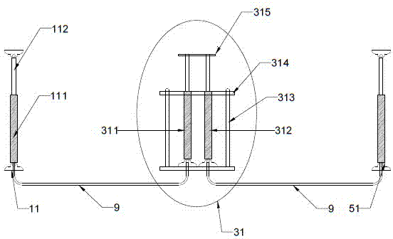
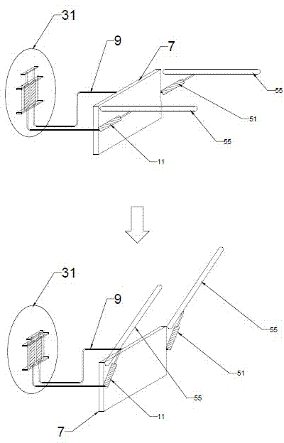
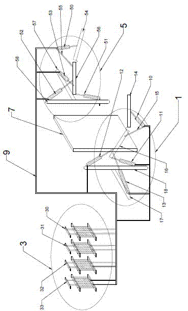
[0021] Such as figure 1 , figure 2 , image 3 as shown, figure 1 It is a schematic diagram of the power conversion mechanism of the present invention; figure 2 It is a working principle diagram of the system of the present invention; image 3 It is a schematic diagram of the upper limb auxiliary exercise device of the present invention.

[0022] The intelligent auxiliary movement device for upper limbs of this embodiment is composed of a left mechanical arm exoskeleton 1, a right mechanical arm exoskeleton 5 and a power conversion mechanism.

[0023] The left mechanical arm exoskeleton 1 is composed of the left mechanical arm elbow joint dimension control hydraulic cylinder 10, the left mechanical arm shoulder joint lower dimension control hydraulic cylinder 11, the hydraulic cylinder cylinder block 111, th...


PUM


Abstract

The invention discloses an intelligent upper limb auxiliary motion device which is composed of mechanical ectoskeletons and a power conversion mechanism. Each mechanical ectoskeleton comprises a mechanical arm, an elbow joint control mechanism, a shoulder joint control mechanism, a shoulder shaft and a back plate. The power conversion mechanism comprises a left dimension control hydraulic cylinder, a power convertor and a right dimension control hydraulic cylinder, the left dimension control hydraulic cylinder is connected with the power converter through an oil pipe, and the right dimension control hydraulic cylinder is connected with the power converter through an oil pipe. A hydraulic system is adopted in the intelligent upper limb auxiliary motion device which is simple in structure and high in reliability. The upper limbs of a patient serve as power sources, and no external power supply is needed, so that the intelligent upper limb auxiliary motion device is safe and reliable, and secondary injury risks are avoided. Meanwhile, the intelligent upper limb auxiliary motion device further can be used at home, and therefore, rehabilitation expenditure of the patient is greatly reduced.

Description

technical field [0001] The invention relates to an auxiliary exercise device, in particular to an upper limb rehabilitation training device. Background technique [0002] The vast majority of stroke patients and some patients with accidental upper limb injuries need long-term and high-frequency rehabilitation training for the affected limbs after surgery, especially for stroke patients. After the operation is completed and the initial rehabilitation in the hospital is completed, the patient Will go back home, in order to enable the affected limb to move frequently and not shrink, the patient needs to regularly go to the rehabilitation center for rehabilitation training, which brings great inconvenience to the patient and their families. [0003] There are three main methods of upper limb rehabilitation training: rehabilitation training performed by medical technicians, rehabilitation devices that perform circular motions similar to bicycle pedals, and mechanical arms similar...

Claims


Application Information

Patent Timeline
IPC IPC(8): A61H1/02
Inventor 蒋文庆
Owner 蒋文庆
Learn More