

Radiotherapy device
A radiotherapy and equipment technology, applied in the field of radiotherapy equipment, can solve the problems of inability to accurately monitor patient parts, difficult early cancer monitoring, etc., and achieve the effect of improving treatment accuracy and efficiency
- Summary
- Abstract
- Description
- Claims
- Application Information
AI Technical Summary
Problems solved by technology
Method used
Image

Examples
no. 1 example
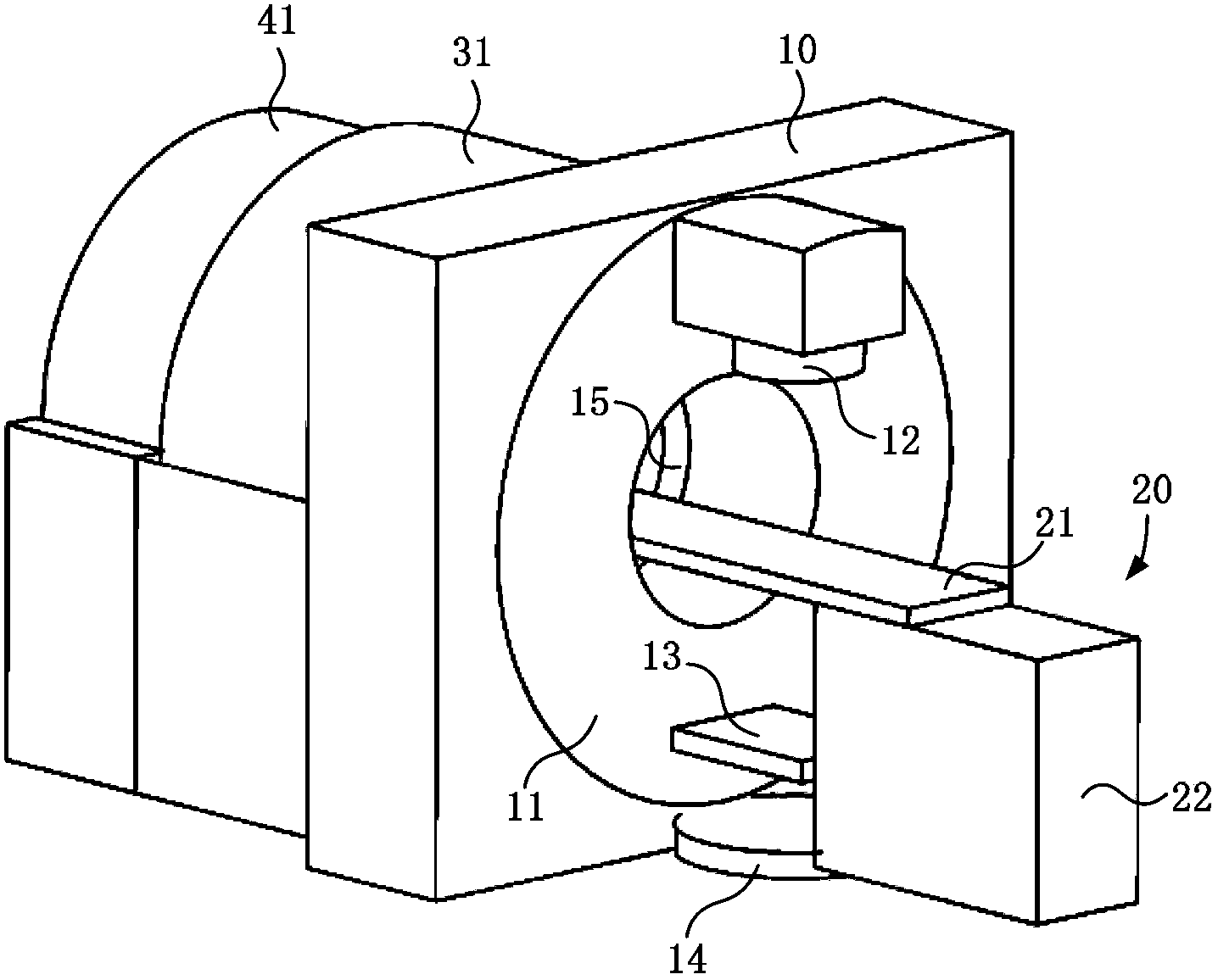
[0042] The following reference Figure 2 to Figure 5 The first embodiment according to the present invention will be described in detail.
[0043] figure 2 Is a schematic front view of the first embodiment of the radiotherapy equipment of the present invention; image 3 It is a schematic diagram of the back of the first embodiment of the radiotherapy equipment of the present invention; Figure 4 Is a schematic side view of the first embodiment of the radiotherapy equipment of the present invention; Figure 5 It is a schematic diagram of the "T"-shaped stent of the radiotherapy equipment of the present invention. Such as Figure 2 to Figure 5 As shown, the radiotherapy equipment includes a radiotherapy unit 10, a hospital bed 20, a PET monitoring unit 31, and a CT monitoring unit 41. The radiotherapy unit 10 includes an accelerator 12 for emitting radiation; a detector 13 perpendicular to the central radiation emitted by the accelerator 12 and in a planar shape, used to determin...
no. 2 example
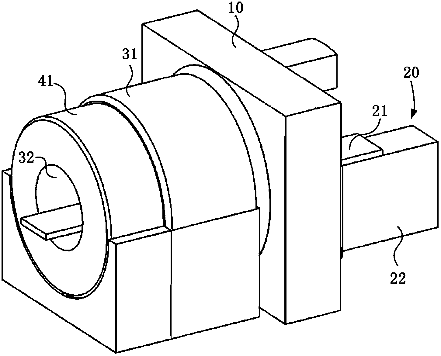
[0050] The following reference Figure 5 , Image 6 The second embodiment according to the present invention will be described in detail.
[0051] Figure 5 Is a schematic diagram of the "T"-shaped bracket of the radiotherapy equipment of the present invention; 6 is a schematic side view of the second embodiment of the radiotherapy equipment of the present invention. Such as Image 6 The illustrated radiotherapy equipment includes a radiotherapy unit 10, a hospital bed 20, a PET monitoring unit 31, and a CT monitoring unit 41. The radiotherapy unit 10 includes an accelerator 12 for emitting radiation; a detector 13 perpendicular to the central radiation emitted by the accelerator 12 and in a planar shape, used to determine the contour shape of the therapeutic radiation beam. The detector 13 can be folded or stored according to requirements In the radiotherapy unit 10, in the initial state, the accelerator 12 and the detector 13 are respectively located above and below the patient...
no. 3 example
[0059] The following reference Figure 5 , Figure 7 The third embodiment according to the present invention will be described in detail.
[0060] Figure 5 It is a schematic diagram of the "T"-shaped bracket of the radiotherapy equipment of the present invention; Figure 7 It is a schematic side view of the third embodiment of the radiotherapy equipment of the present invention. Such as Figure 7 The illustrated radiotherapy equipment includes a radiotherapy unit 10, a hospital bed 20, a PET monitoring unit 31, and a CT monitoring unit 41. The radiotherapy unit 10 includes an accelerator 12 for emitting radiation; a detector 13 perpendicular to the central radiation emitted by the accelerator 12 and in a planar shape, used to determine the contour shape of the therapeutic radiation beam. The detector 13 can be folded or stored according to requirements In the radiotherapy unit 10, in the initial state, the accelerator 12 and the detector 13 are respectively located above and bel...
PUM
 Abstract
Description
Claims
Application Information