Cast-in-place light-weight foamed concrete construction technique

A technology of foam concrete and construction technology, which is applied in the field of construction engineering, can solve problems such as foam concrete laying and cracks, achieve the effect of stabilizing the bubbles and reducing labor input

Active Publication Date: 2014-10-29
CHINA METALLURGICAL CONSTR ENG GRP
View PDF4 Cites 17 Cited by
  • Summary
  • Abstract
  • Description
  • Claims
  • Application Information

AI Technical Summary

Problems solved by technology

[0004] The object of the present invention is to provide a construction technology of cast-in-place lightweight foam concrete that do

Method used


Image

  • Cast-in-place light-weight foamed concrete construction technique
  • Cast-in-place light-weight foamed concrete construction technique

Examples


Example Embodiment

[0053] Example 1:

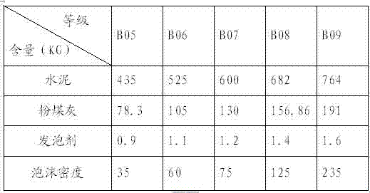
[0054] Prepare cement slurry solution: add 435kg cement, 78.3kg fly ash, and 174kg water to the mixing hopper I of the hydraulic foaming machine and stir for 0.7min. The weight ratio of the above cement, fly ash and water is 1:0.18:0.4 .

[0055] Prepare the foaming agent aqueous solution: add 0.9 kg foaming agent and 58.5 kg of water to the mixing hopper II of the foaming hydraulic press and stir for 4 minutes. The weight percentage of the foaming agent and water is 1:65. After stirring, the foam density is 35㎏ / m 3 .

[0056] Preparation of foamed concrete: the above-mentioned foaming agent aqueous solution is put into the cement slurry solution and stirred for 2 minutes, and the weight percentage of the foaming agent aqueous solution and the cement slurry solution is 1:13.8.

Example Embodiment

[0057] Example 2:

[0058] Preparation of cement slurry solution: add 525 kg cement, 105 kg fly ash, and 262.5 kg water to the mixing hopper I of the hydraulic foaming machine and mix for 0.5 min. The weight ratio of the above cement, fly ash, and water is 1:0.2:0.5.

[0059] Preparation of the foaming agent aqueous solution: adding 1.1 kg foaming agent, 74.8 kg of water foaming hydraulic press and stirring in the mixing hopper II for 5 minutes, the weight percentage of the foaming agent and water is 1:68. After stirring, the foam density is 60㎏ / m 3 .

[0060] Preparation of foamed concrete: the above-mentioned foaming agent aqueous solution is put into the cement slurry solution and stirred for 1.5 minutes, and the weight percentage of the foaming agent aqueous solution and the cement slurry solution is 1:12.

Example Embodiment

[0061] Example 3:

[0062] Preparation of cement slurry solution: add 600 kg cement, 130 kg fly ash, and 390 kg water to the mixing hopper I of the hydraulic foaming machine and mix for 0.8 min. The weight ratio of the above cement, fly ash and water is 1:0.22:0.65.

[0063] Prepare the foaming agent aqueous solution: add 1.2 kg foaming agent and 84 kg water to the mixing hopper II of the foaming hydraulic press and stir for 3 minutes. The weight percentage of the foaming agent and water is 1:70. After stirring, the foam density is 75㎏ / m 3 .

[0064] Preparation of foamed concrete: the above-mentioned foaming agent aqueous solution is put into the cement slurry solution and stirred for 1.5 minutes, and the weight percentage of the foaming agent aqueous solution and the cement slurry solution is 1:13.


PUM


Abstract

The invention discloses a cast-in-place light-weight foamed concrete construction technique. The technique comprises the following steps: earlier stage preparation; cement mortar solution preparation: mixing cement and fly ash in a mixing hopper; foaming agent water solution preparation: weighing a foaming agent, adding the foaming agent and water into a mixing hopper of a hydraulic foaming machine, uniformly mixing to form the foaming agent water solution; foamed concrete preparation: gradually adding the foaming agent water solution prepared in the step 2 into the cement mortar solution by a conveyer belt, mixing for 1-3 minutes to form the foamed concrete; discharging the mortar and delivering the foamed concrete; casting the foamed concrete; and curing. The foamed concrete can not easily collapse in the in-place casting process, and has the advantages of high construction speed and low construction cost.

Description

Technical field [0001] The invention relates to the field of building construction engineering, in particular to the construction process of pouring lightweight foam concrete on site. Background technique [0002] Foamed concrete wall is a new type of thermal insulation material. Because of its remarkable thermal insulation effect, low physical properties, low temperature and low cost, it is widely used in the construction industry. [0003] At present, the construction method of foam concrete wall is that in the original cavity material, the aerated concrete wall is prone to cracks. During the pouring process, due to the weak structure, lack of toughness, and easy rupture of some bubbles, the air will run away after the bubbles burst. The slurry lacks the collective support of air bubbles and causes a stay. In addition, when preparing the cement slurry solution, the amount of cement and fly ash should not be controlled, and the quality will be biased, leading to cracks on the wa...

Claims


Application Information

Patent Timeline
IPC IPC(8): C04B38/10C04B28/00
Inventor 熊伟何俨程国富冯毅
Owner CHINA METALLURGICAL CONSTR ENG GRP
Why Eureka
Try Eureka