Drilled hole effective extraction radius measuring method based on gas content method

A technology of gas content and gas drainage, which is applied in the field of measuring the effective drainage radius of boreholes based on the gas content method, can solve the problems of low success rate, save manpower and eliminate outburst risks

Inactive Publication Date: 2014-10-29
CHINA COAL TECH ENG GRP CHONGQING RES INST
8 Cites 26 Cited by

AI-Extracted Technical Summary

Problems solved by technology

[0004] In view of this, the purpose of the present invention is to overcome the above-mentioned deficiencies and provide a method for measuring the effective drainage radius of...

Abstract

The invention provides a drilled hole effective extraction radius measuring method based on a gas content method, and belongs to the technical field of coal seam gas extraction. The method comprises the following steps that (1) the gas extraction rates under the different residual gas content conditions are respectively calculated; (2) the gas extraction rate eta 5 is determined according to the regulations of the Coal Mine Gas Extraction Basic Index; (3) the gas extraction rate eta is calculated; (4) the total extraction quantity of gas is calculated; (5) the number N of extraction drilled holes is calculated; (6) the N drilled holes are evenly distributed in an extraction drilled hole control area, and the drilled hole extraction radius within certain extraction time is calculated. The effective extraction radius can guide to design the reasonable extraction drilled holes, the aim of eliminating prominent dangerousness can be achieved through the method on the premise of meeting the pre-extraction time, and a large amount of manpower and a large number of financial resources and material resources can be saved.

Application Domain

Technology Topic

Image

  • Drilled hole effective extraction radius measuring method based on gas content method
  • Drilled hole effective extraction radius measuring method based on gas content method
  • Drilled hole effective extraction radius measuring method based on gas content method

Examples

  • Experimental program(1)

Example Embodiment

[0041] The following is a detailed description of the preferred embodiments of the present invention. It should be understood that the preferred embodiments are only for illustrating the present invention, and not intended to limit the protection scope of the present invention.
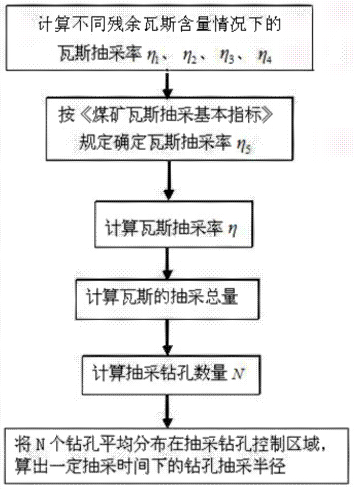
[0042] figure 1 It is a schematic flow chart of the method for determining the effective extraction radius of a borehole based on the gas content method of the present invention, with reference to figure 1 , The present invention includes the following steps:
[0043] 1) Calculate the gas drainage rate under different residual gas content, including: the residual gas volume is reduced to 8m 3 /t gas drainage rate η 1 、The gas drainage rate η when the residual gas content is reduced to the corresponding gas content at the depth of the initial outburst 2 、When the residual gas pressure is reduced to 0.74MPa, the gas extraction rate η corresponding to the gas content 3 、The gas drainage rate η corresponding to the gas content when the residual gas pressure is reduced to the gas pressure at the depth of the outburst 4;
[0044] 2) Determine the gas drainage rate η according to the "Basic Indicators of Coal Mine Gas Drainage" 5;
[0045] 3) Calculate the gas drainage rate η according to formula (1):
[0046] η=max(η 1 ,η 2 ,η 3 ,η 4 ,η 5 ) (1)
[0047] 4) Calculate the total amount of gas drainage according to formula (2):
[0048] Q total =L 1 ×L 2 ×h×γ×W×η (2)
[0049] Where: L 1 , L 2 Is the length and width of the drainage borehole control area; h is the coal seam thickness in the drainage borehole control area; γ is the coal density in the drainage borehole control area; W is the original gas content of the coal seam in the drainage borehole control area;
[0050] 5) Calculate the number of drainage holes N:
[0051] N=Q total /Q single (3)
[0052] Where: Q single It is the single-hole drainage volume counted within the drainage time;
[0053] 6) Evenly distribute N boreholes in the control area of ​​the drainage boreholes, and calculate the drainage radius of the boreholes under a certain drainage time:
[0054] 6-1) Boundary drilling radius r 1 Use the following formula:
[0055] r 1 = L 1 2 N - - - ( 4 )
[0056] Where: L 1 To control the strike length of the coal seam for drilling holes;
[0057] 6-2) Drainage radius of penetration borehole r 2 Use the following formula:
[0058] r 2 = L 2 2 N - - - ( 5 )
[0059] Where: L 2 Control the side length of the square area of ​​the coal seam for drilling holes.
[0060] It can be seen from the above calculation process that the present invention fully considers the two indicators of gas pressure and gas content, and also considers the gas content and gas pressure at which the residual gas is reduced to the depth of the initial burst. The safety allowable value of gas content is 8m 3 /t, the safe allowable value of gas pressure is 0.74MPa, and the following formulas 6-9 are used to calculate the gas drainage rate under several different conditions. And the calculated gas drainage rate η 1 , Η 2 Determine the gas drainage rate η according to the "Basic Indexes of Coal Mine Gas Drainage" 5 For comparison, the value with the largest drainage rate is selected to calculate the total amount of gas drainage. This can fully meet the coal seam outburst elimination requirements or the gas drainage requirements.
[0061] figure 2 Schematic diagram of bedding drilling layout; image 3 Schematic diagram for the layout of through-layer drilling. Such as figure 2 , image 3 According to the drilling arrangement method shown, the mine chooses the drilling method for construction according to his own situation, and calculates the drainage radius of the bedding drilling and the through-bed drilling according to formulas (4) and (5).
[0062] According to formula (6), the residual gas content is reduced to 8m 3 /t gas drainage rate η 1 :
[0063] η 1 = W - 8 W X 100 % . - - - ( 6 )
[0064] Calculate the gas drainage rate η when the residual gas content is reduced to the corresponding gas content at the depth of the outburst according to formula (7) 2 :
[0065]
[0066] Where: W Beginning Is the corresponding gas content at the depth of the initial protrusion.
[0067] Calculate the gas drainage rate η corresponding to the gas content when the residual gas pressure is reduced to 0.74MPa according to formula (8) 3 :
[0068] η 3 = W - W P - 0.74 W × 100 % - - - ( 8 )
[0069] Where: W P-0.74 It is the corresponding gas content when the gas pressure is reduced to 0.74MPa.
[0070] Calculate the gas extraction rate η corresponding to the gas content when the residual gas pressure is reduced to the gas pressure at the depth of the outburst according to formula (9) 4 :
[0071]
[0072] Where: W P-start It is the gas content corresponding to the gas pressure at the start depth.
[0073] The last point of the present invention is that the above preferred embodiments are only used to illustrate the technical solutions of the present invention and not to limit them. Although the present invention has been described in detail through the above preferred embodiments, those skilled in the art should understand that the Various changes are made to the above and details without departing from the scope defined by the claims of the present invention.

PUM

no PUM

Description & Claims & Application Information

We can also present the details of the Description, Claims and Application information to help users get a comprehensive understanding of the technical details of the patent, such as background art, summary of invention, brief description of drawings, description of embodiments, and other original content. On the other hand, users can also determine the specific scope of protection of the technology through the list of claims; as well as understand the changes in the life cycle of the technology with the presentation of the patent timeline. Login to view more.

Similar technology patents

Method for determining grid type layer-through drilling intervals of floor roadway

InactiveCN102116170AReduce gas contentEliminate outstanding hazardsSurveyGas removalCoalDrill hole
Owner:CHINA UNIV OF MINING & TECH

Classification and recommendation of technical efficacy words

  • Eliminate outstanding hazards
  • Save human effort
Why Eureka
Try Eureka