Supercharge Your Innovation With Domain-Expert AI Agents!

Dual fuel system and engine system method of operation

A dual fuel system, internal combustion engine technology, used in combustion engines, internal combustion piston engines, charging systems, etc., to solve problems and challenges that have not been recognized or solved

Inactive Publication Date: 2017-12-19
CATERPILLAR INC
View PDF4 Cites 0 Cited by
  • Summary
  • Abstract
  • Description
  • Claims
  • Application Information

AI Technical Summary

Problems solved by technology

However, some issues and challenges associated with liquid fuel-only operation have not been recognized or addressed

Method used


Image

  • Dual fuel system and engine system method of operation
  • Dual fuel system and engine system method of operation
  • Dual fuel system and engine system method of operation

Examples


Embodiment Construction

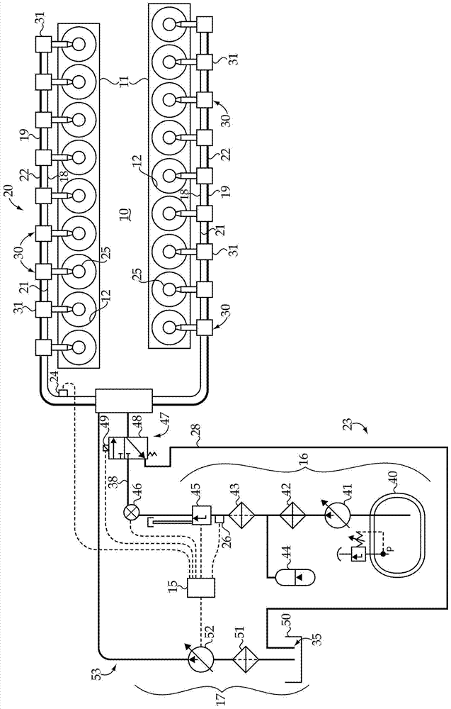
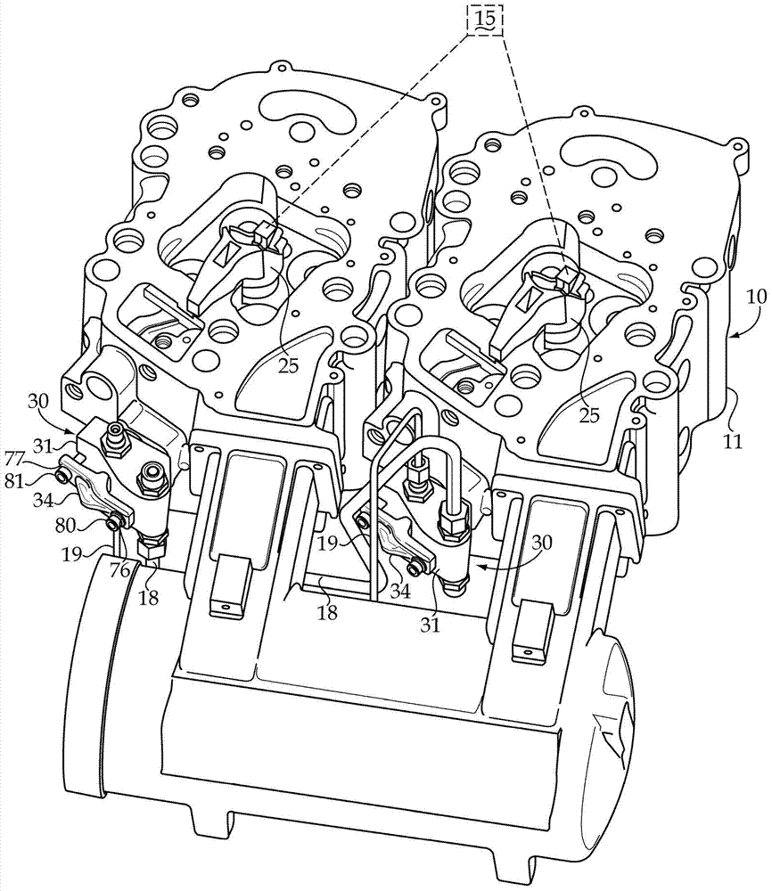
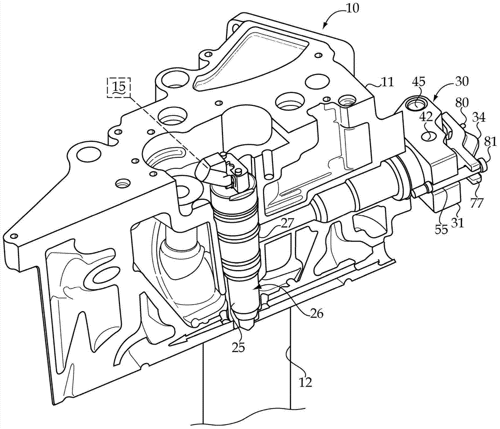
[0013] initial reference Figure 1-3 , the dual fuel engine system 10 includes a dual fuel system 20 mounted to an engine housing 11 defining a plurality of engine cylinders 12 . Dual fuel system 20 may include a unique one fuel injector 25 positioned for direct injection into each of engine cylinders of plurality of engine cylinders 12 . Gaseous fuel manifold 21 and liquid fuel manifold 22 are fluidly connected to each fuel injector 25 and are part of gaseous fuel subsystem 23 and liquid fuel subsystem 53 , respectively, of dual fuel system 20 . Dual fuel system 20 also includes gas supply and pressure control mechanism 16 and liquid supply and pressure control mechanism 17 fluidly connected to manifold 21 and manifold 22, respectively. Gaseous fuel conduit 38 fluidly connects mechanism 16 to manifold 21 by way of shutoff valve 46 discussed further herein. Each of fuel injector 25 , gas supply and pressure control mechanism 16 and liquid supply and pressure control mechanis...


PUM


Abstract

The present invention discloses a dual fuel system and engine system operating method. Specifically, a dual fuel system for internal combustion engines comprises a gas-fuel subsystem and a liquid-fuel subsystem. A plurality of fuel injectors each limit the gas fuel channel to the gas fuel manifold of the gas fuel subsystem, the liquid fuel channel of the liquid fuel manifold fluidly connected to the liquid fuel subsystem, and the liquid fuel leakage path from the liquid fuel channel to the gas fuel channel. A liquid fuel cleaning mechanism comprises an exhaust pipe and a fluidly positioned at least one valve between the discharge pipe and the gas fuel manifold, the at least one valve may be adjusted so that the discharge pipe is fluidly connected to the gas fuel manifold, to discharge the leaking liquid fuel to a low-pressure outlet.

Description

technical field [0001] The present invention relates generally to dual fuel systems for internal combustion engines, and more particularly to purging liquid fuel that has leaked into the gaseous fuel side of the system. Background technique [0002] A relatively new type of engine attempts to utilize two different fuels to obtain the efficiencies associated with compression ignition, combined with the advantages associated with burning gaseous fuels, such as natural gas. Specifically, a dual fuel engine utilizes a small pilot injection of liquid diesel fuel that is compression ignited to in turn ignite a larger charge of natural gas fuel in each engine cylinder. In one strategy for this type of engine, both fuels are injected directly from a single fuel injector associated with each engine cylinder. [0003] For example, US Patent 7627416 appears to teach a dual fuel common rail system in which both liquid diesel fuel and natural gas fuel are injected from a single fuel inj...

Claims


Application Information

Patent Timeline
Patent Type & Authority Patents(China)
IPC IPC(8): F02B69/04F02M21/02F02B77/04F02M43/04F02D19/06
CPCF02M21/0281F02D19/0621F02D19/0647F02D19/0694F02D19/105F02M63/0295F02M43/04F02M47/027F02M55/002F02M55/02F02M63/0019F02M2200/44F02M63/0064Y02T10/30F02M21/0284
Inventor 房殿奇D·帕克特
Owner CATERPILLAR INC
Features
  • R&D
  • Intellectual Property
  • Life Sciences
  • Materials
  • Tech Scout
  • Unparalleled Data Quality
  • Higher Quality Content
  • 60% Fewer Hallucinations
Learn More