Lubricating oil replacing device for nuclear power plant

A technology for replacing equipment and lubricating oil, applied in the direction of mechanical equipment, lubricating parts, engine lubrication, etc., can solve the problems of simple structure, shorten the service life, lubricating oil pollution, etc., achieve simple and compact structure, prolong the service life, avoid The effect of pollution

Active Publication Date: 2014-10-29
CHINA NUCLEAR POWER TECH RES INST CO LTD +2
View PDF7 Cites 5 Cited by
  • Summary
  • Abstract
  • Description
  • Claims
  • Application Information

AI Technical Summary

Problems solved by technology

[0004] At present, most of the lubricating oil replacement or replenishment of large-scale mechanical equipment such as main pump motors in nuclear power plants requires manual power to operate simple manual oil change devices to extract the old lubricating oil from the mechanical equipment and replace the new one. The lubricating oil is injected into the mechanical equipment. This manual oil change device has the defects of simple structure, cumbersome and complicated operation, extremely labor-intensive, extremely low efficiency, very inconvenient to use and very high maintenance cost; The defect that the lubricating oil cannot be completely drained causes the new lubricating oil injected into the mechanical equipment to be polluted and shorten the service life
However, there are new automatic or semi-automatic mechanical oil change devices for replacing or replenishing lubricating oil in mechanical equipment. This automatic or semi-automatic mechanical oil change device has extremely complicated structure, high manufacturing cost, and extremely cumbersome operation. Complicated and very difficult to maintain

Method used


Image

  • Lubricating oil replacing device for nuclear power plant
  • Lubricating oil replacing device for nuclear power plant
  • Lubricating oil replacing device for nuclear power plant

Examples


Embodiment Construction

[0026] In order to describe the technical content and structural features of the present invention in detail, further description will be given below in conjunction with the implementation and accompanying drawings.

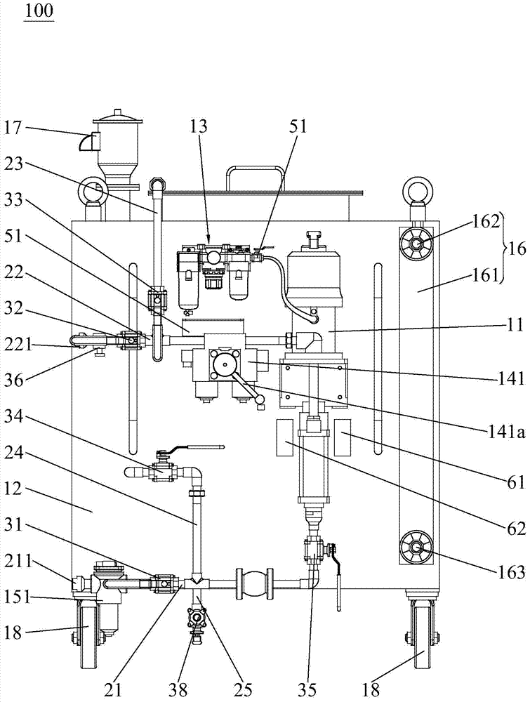
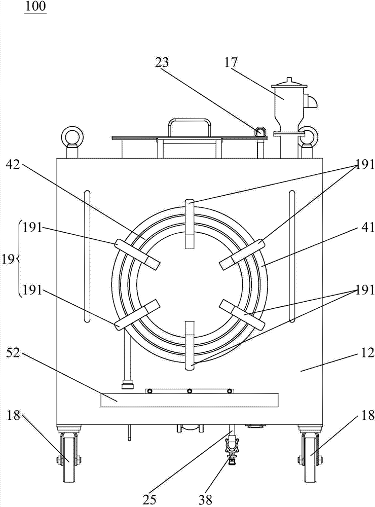
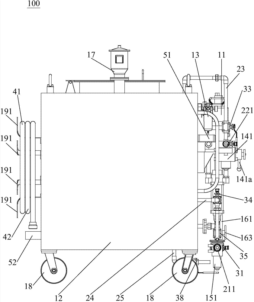
[0027] see Figure 1 to Figure 3 , the lubricating oil replacement equipment 100 for nuclear power of the present invention comprises an automatic oil pump (not marked in the figure), an oil suction pipe 21, an oil supply pipe 22, an oil inlet pipe 23, an oil outlet pipe 24 and an oil storage tank 12 for storing lubricating oil, an oil suction pipe 21 is provided with a first valve 31, the oil supply pipe 22 is provided with a second valve 32, the oil inlet pipe 23 is provided with a third valve 33, and the oil outlet pipe 24 is provided with a fourth valve 34; the oil storage tank 12 is provided with an oil inlet (in the figure not shown) and oil outlet (not shown in the figure), in detail, in the present embodiment, the oil inlet is opened on the top of the oil...


PUM


Abstract

The invention provides a lubricating oil replacing device for a nuclear power plant. The lubricating oil replacing device comprises an automatic oil pump, an oil pumping pipe, an oil supplying pipe, an oil inlet pipe, an oil outlet pipe and an oil storage tank for storing lubricating oil. The oil pumping pipe is provided with a first valve, the oil supplying pipe is provided with a second valve, the oil inlet pipe is provided with a third valve, and the oil outlet pipe is provided with a fourth valve. The oil storage tank is provided with an oil inlet and an oil outlet, one end of the oil outlet pipe is connected with the oil outlet, both the other end of the oil outlet pipe and one end of the oil pumping pipe are connected with the input end of the automatic oil pump, and the other end of the oil pumping pipe is an oil pumping connecting end. One end of the oil inlet pipe is connected with the oil inlet, both the other end of the oil inlet pipe and one end of the oil supplying pipe are connected with the output end of the automatic oil pump, and the other end of the oil supplying pipe is an oil supplying connecting end. The lubricating oil replacing device for the nuclear power plant has the advantages of being simple and compact in structure, low in manufacturing cost, easy to maintain, free of manual power providing, easy and convenient to operate, capable of saving labor, efficient in lubricating oil replacement, and capable of discharging old lubricating oil in mechanical equipment completely.

Description

technical field [0001] The invention relates to the field of lubricating oil replacement equipment, in particular to lubricating oil replacement equipment for nuclear power plants. Background technique [0002] The lubrication management of mechanical equipment is an important part of the technical management of mechanical equipment, and it is also an important part of the maintenance of mechanical equipment. Doing a good job in the lubrication of mechanical equipment is to ensure the normal operation of mechanical equipment, reduce equipment wear, prevent and reduce equipment accidents, and reduce power consumption. , Effective measures to extend the repair cycle and service life of equipment. [0003] As we all know, when the lubricating oil in the mechanical equipment reaches the service life or the content is insufficient, the lubricating oil in the mechanical equipment needs to be replaced or replenished. Among them, when replacing the lubricating oil in the mechanical...

Claims


Application Information

Patent Timeline
Patent Type & Authority Applications(China)
IPC IPC(8): F16N31/00
Inventor 侯硕梁琼刘青松董志国余冰顾伟董亚超王超沈黎陈嘉杰邓志燕王国河薛晓攀贺韶魏超
Owner CHINA NUCLEAR POWER TECH RES INST CO LTD
Why Eureka
Try Eureka