
Adjustable Y-type furnace wall grasping nail structure

An adjustable furnace wall technology, applied in the direction of combustion method, combustion chamber, outer cover/lining, etc., can solve the problems of lower work efficiency, different thickness of refractory materials, heavier design, production workload, etc., to improve work efficiency, good versatility

Inactive Publication Date: 2014-10-29
WUXI HUAGUANG BOILER
View PDF5 Cites 3 Cited by
  • Summary
  • Abstract
  • Description
  • Claims
  • Application Information

AI Technical Summary

Problems solved by technology

The existing application number is 2013103987595, and the publication date is December 18, 2013, a nail structure for fixing refractory materials for boilers, which discloses the following technical features: "It includes a head structure and a tail structure, and the tail structure The upper part of the structure protrudes outwards, and the head structure is an angled outward flaring structure. The center lower part of the mouth structure is welded and connected after the bending position of the lower part of the mouth structure", that is, the Y-shaped furnace wall nail is disclosed, but the length of the metal nails for fixing the furnace wall refractory material in the existing Y-shaped furnace wall nails is fixed. The thickness of the refractory material in different parts is different
In this way, each design must be designed according to the different requirements of customers with various lengths of nails, which greatly increases the workload of design and production and reduces work efficiency.

Method used


Image

  • Adjustable Y-type furnace wall grasping nail structure
  • Adjustable Y-type furnace wall grasping nail structure

Examples


specific Embodiment 1

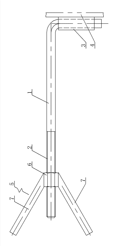
[0011] Specific embodiment one, see figure 1 : it includes a V-shaped head structure 5 and an L-shaped moment arm structure 1, the connection position of the V-shaped head structure 5 is specifically a nut structure 6, and the outer walls on both sides of the nut structure 6 are respectively welded and connected to metal rods 7, The metal rods 7 on both sides are combined to form a V-shaped structure and are located in the same plane. The nut structure 6 is screwed to the external thread structure 2, and the metal rod 7 is a round steel structure.

specific Embodiment 2

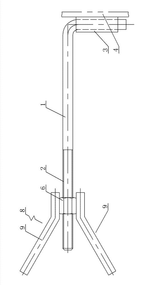
[0012] Specific embodiment two, see figure 2 : It includes a Y-shaped head structure 8, the metal rods on both sides are respectively bent to form symmetrical bent metal rods 9, the bent metal rods 9 are round steel structures, and the mutually parallel parts 10 of the bent metal rods 9 on both sides are The nut structure 6 is welded between them, and the bent metal rods 9 on both sides are welded to form a Y-shaped structure and are located in the same plane; the nut structure 6 is threaded to the external thread structure 3, and the bent metal rods 9 is a round steel structure.

[0013] The nut structures in the specific embodiment 1 and the specific embodiment 2 are all standard nuts. The grab nails are combined with ordinary steel components, which avoids the problems of air holes, shrinkage cavities and slag inclusions that may occur in castings; and the grab nails are welded by round steel and standard nuts, which is easy to manufacture.


PUM


Abstract

The invention provides an adjustable Y-type furnace wall grasping nail structure. Due to the structure, the length of Y-type furnace wall grasping nails can be adjusted according to the thickness of refractory materials, then the Y-type furnace wall grasping nails are high in generality, the design and production workload is reduced, and working efficiency is improved. The adjustable Y-type furnace wall grasping nail structure comprises a V-type head structure and an L-type force arm structure and is characterized in that the connection position of the V-type head structure is concretely of a nut structure, the outer walls on the two sides of the nut structure are respectively connected with a metal rod in a welded mode, the metal rods on the two sides are combined to form the V-type structure and are located in the same plane, one end of the L-type force arm structure is machined to be of an external thread structure, and the nut structure is in threaded connection with the external thread structure.

Description

technical field [0001] The invention relates to the technical field of fixing furnace wall refractory materials, in particular to an adjustable Y-shaped furnace wall nail structure. Background technique [0002] As a thermal equipment, boilers are widely used in various fields. The boiler burns various fuels, and the temperature of the flue gas is very high. It is often necessary to build refractory insulation materials for heat preservation. The refractory materials are relatively thick in high temperature areas, and refractory and thermal insulation castables are often used for construction convenience. The existing application number is 2013103987595, and the publication date is December 18, 2013, a nail structure for fixing refractory materials for boilers, which discloses the following technical features: "It includes a head structure and a tail structure, and the tail structure The upper part of the structure protrudes outwards, and the head structure is an angled out...

Claims


Application Information

Patent Timeline
IPC IPC(8): F23M5/04
Inventor 潘甜甜吴琦玲朱清龚菲陈益增
Owner WUXI HUAGUANG BOILER
Learn More