Ratiometric detection methods in fluorescent probes

A detection method and fluorescent probe technology, which are applied in the fields of fluorescent probes, ratiometric fluorescent probes and time-resolved fluorescence spectroscopy, can solve the problems of complex fluorescence decay curves and inability to obtain satisfactory fitting effects, and achieve the realization of ratiometric fluorescence measurement. Effect

Active Publication Date: 2016-08-24
江苏鲲鹏未来光学有限公司
View PDF4 Cites 0 Cited by
  • Summary
  • Abstract
  • Description
  • Claims
  • Application Information

AI Technical Summary

Problems solved by technology

However, the fluorescence decay curve is usually complex, and a satisfactory fitting effect cannot be obtained by single-exponential fitting. In this case, multi-exponential fitting is required. fitting, where

Method used


Image

  • Ratiometric detection methods in fluorescent probes
  • Ratiometric detection methods in fluorescent probes
  • Ratiometric detection methods in fluorescent probes

Examples


Embodiment 1

[0021] Example 1: Realization of a quantitative and highly sensitive measurement method in a circular green fluorescent protein (cpGFP)-based NADH probe.

[0022] In this example, the NADH-sensitive fluorescent protein probe reported in Cell Metabolism 14, 545–554, 2011 was used, but the mCherry red fluorescent protein part was removed through genetic engineering, and only the Peredox part was retained.

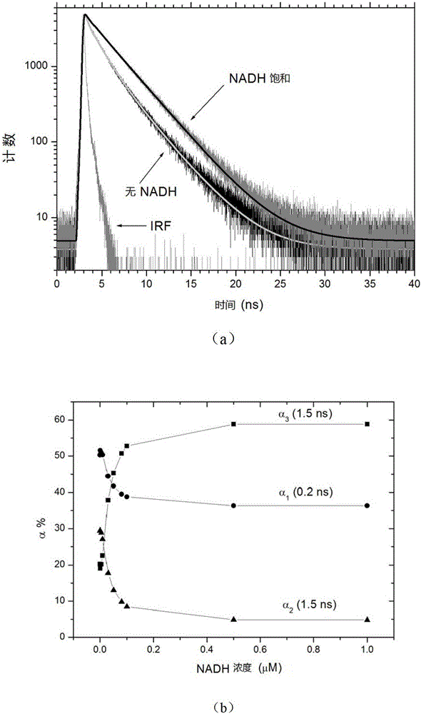
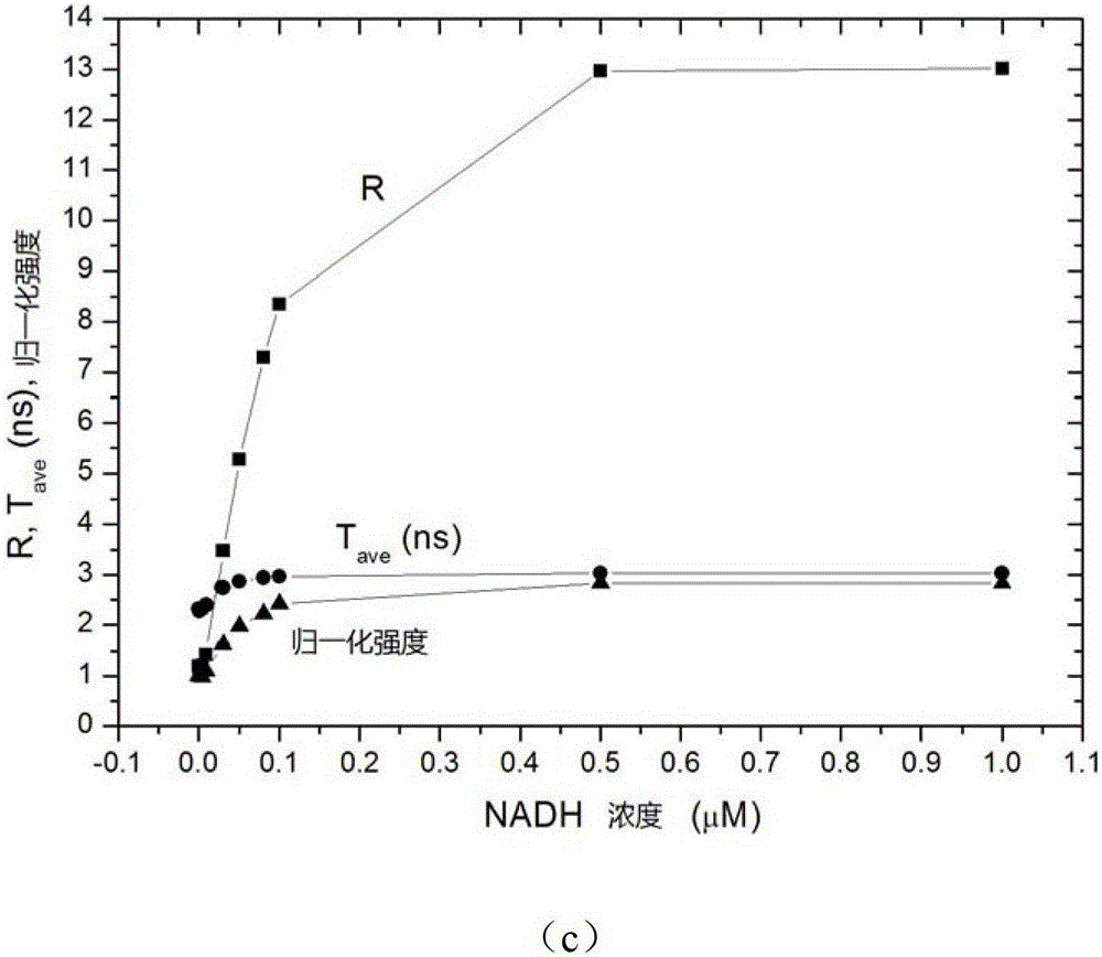
[0023] figure 1 (a) shows the time-resolved fluorescence curves of Peredox in the absence of NADH and after NADH saturation. By fitting the instrument response function IRF and the mathematical model The reconvolution of (i=1..3) can obtain the values ​​of n groups of parameters α and τ in the model with high precision, and n is a natural number. In this embodiment, n is set to 3, that is, three sets of values ​​of α and τ are obtained.

[0024] figure 1 (b) shows the relationship between Peredox protein fluorescence fitting parameters α1 (0.2ns), α2 (1.5ns), and α3 (3.2...

Embodiment 2

[0026] Example 2: Realization of a quantitative and highly sensitive measurement method in the circular yellow fluorescent protein (cpYFP)-based NADH probe SuperFrex.

[0027] This SuperFrex is a newly invented protein through genetic technology, and the fluorescent chromophore in SuperFrex is yellow fluorescent protein YFP. This kind of protein is based on the traditional steady-state fluorescence measurement method, which usually uses two excitation wavelengths of 420nm and 490nm to excite, and detects the intensity of its emitted fluorescence at around 514nm and takes its ratio to achieve ratiometric measurement.

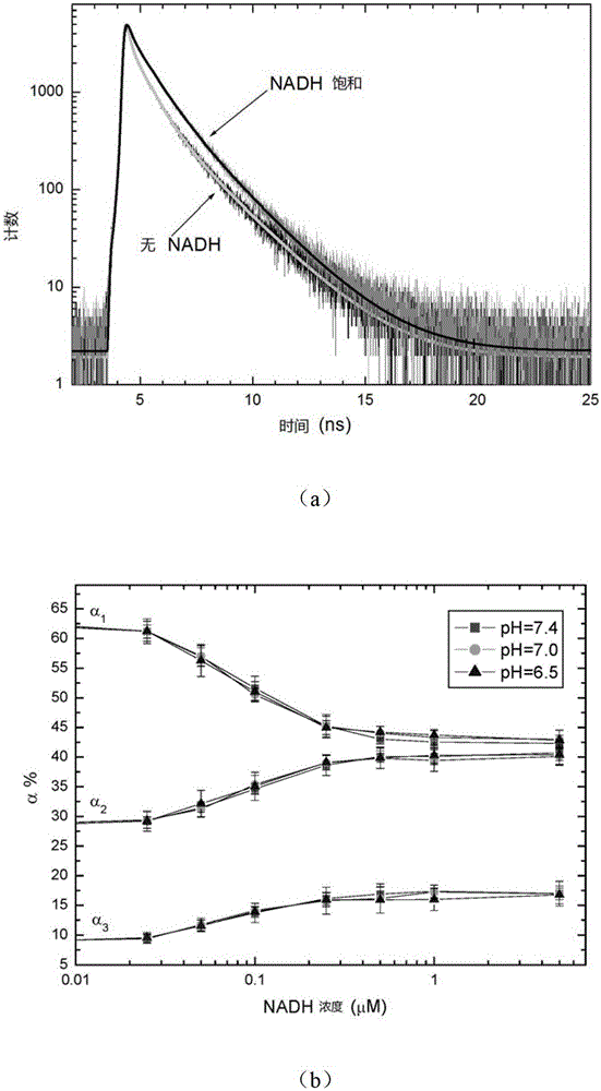
[0028] figure 2 (a) shows the time-resolved fluorescence curve of the SuperFrex protein excited at 420nm and detected at 514nm in the absence of NADH (No NADH) and NADH saturation. Three sets of α and τ values ​​can be obtained through fitting.

[0029] figure 2 (b) shows the relationship between α1 (about 0.15 ns), α2 (about 0.8 ns), and α3 (about 1.9 ns) a...


PUM


Abstract

The present invention proposes a ratio detection method in a fluorescent probe, which includes the following steps: (a) making the fluorescent probe measure the substance to be tested, and using time-resolved fluorescence spectroscopy to measure and obtain the fluorescence decay curve of the probe; (b) ) combined with a multi-exponential model by a fitting algorithm , fitting the fluorescence decay curve, extracting the corresponding values ​​of αn and τn, where n is a natural number; (c) according to the variation trend of the values ​​of αn and τn with the detected substances, divide αn and τn into two types of data: One type increases with the increase of detection substances, marked as αn+ and τn+, and the other type decreases with the increase of detection substances, marked as αn- and τn-; (d) Calculate the ratio of the above two types of data to achieve the ratio of detection substances Measurement. The method of the invention only needs one excitation wavelength and one detection wavelength, and the fluorescence ratio detection can be carried out by calculating the ratio of different lifetime components in the transient fluorescence curve.

Description

technical field [0001] The invention relates to the field of fluorescent probes, in particular to the technical fields of ratio fluorescent probes and time-resolved fluorescence spectroscopy. Background technique [0002] Fluorescent probes have a wide range of applications, and people have designed a variety of fluorescent probes to detect the pH value of the solution, the concentration of metal ions in the solution, and so on. When the amount (or concentration) of the detected substance changes, the fluorescence intensity of the probe generally changes accordingly. At the same time, the fluorescence intensity emitted by the probe is also affected by many factors, such as: the power of the excitation light, the concentration of the fluorescent probe, the optical element, the efficiency of the detector, the quenching of the sample, etc. Therefore, for quantitative measurement, the general tendency is Because the fluorescent probe is required to be a ratiometric fluorescent ...

Claims


Application Information

Patent Timeline
IPC IPC(8): G01N21/64
Inventor 潘海峰刘梦薇梁荣荣常孟方秦翠芳张三军徐建华
Owner 江苏鲲鹏未来光学有限公司
Why Eureka
Try Eureka