
Loadable industrial CT (computed tomography) detection device

A detection device, an industrial technology, applied in the field of non-destructive radiation testing and computer tomography, which can solve the problems of limited load bearing capacity, inability to complete real-time CT detection, and the influence of X-ray penetration ability.

Inactive Publication Date: 2014-10-29
CHONGQING UNIV +1
View PDF5 Cites 19 Cited by
  • Summary
  • Abstract
  • Description
  • Claims
  • Application Information

AI Technical Summary

Problems solved by technology

Invention patent CN101738403A provides an automatic loading system for industrial CT test benches. This invention designs an electric mechanical loading device and transmits command signals wirelessly, and still uses the traditional CT scanning method of rotating test objects. , the cable must be connected during the loading process, so it is still impossible to complete the real-time CT detection in the variable load state, but can only be loaded once and remove the cable for a CT scan, then connect the cable and load it again and remove the cable again for a CT scan Scanning, and so on; however, this method has made great progress compared with the traditional method, but the load bearing capacity of this mechanical device is also limited, in order to increase its load bearing capacity, the thickness of the metal shell must be thickened In order to increase the intensity, another problem brought about by this is that the penetrating ability of X-rays is also affected, and more energy is required to penetrate the loading device and test object

Method used


Image

  • Loadable industrial CT (computed tomography) detection device
  • Loadable industrial CT (computed tomography) detection device

Examples


Embodiment Construction

[0019] The preferred embodiments of the present invention will be described in detail below with reference to the accompanying drawings.

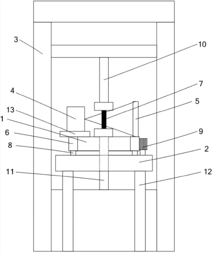
[0020] figure 1 It is a front view of the device of the present invention, as shown in the figure, the device includes a frame 2, a CT scanning device 1 installed on the frame 2, a loading test stand 3, an operation console and an image reconstruction processing device;

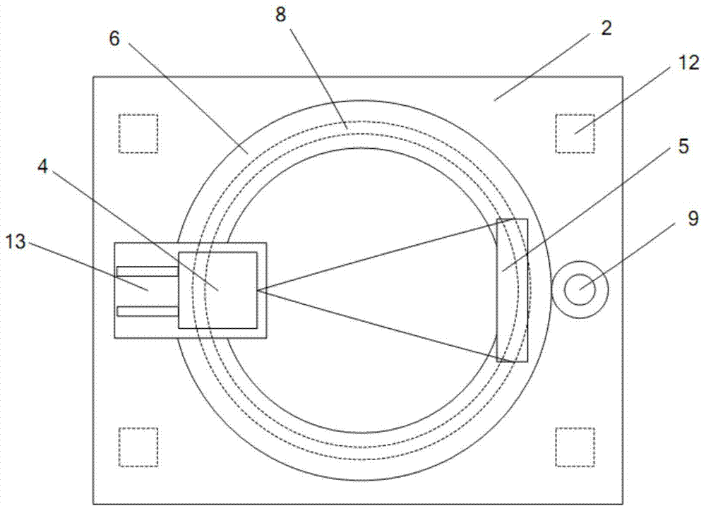
[0021] The CT scanning device 1 is circular. In the CT scanning device, the radiation source 4 and the detector 5 are fixed on a circular ring 6, and the circular ring 6 performs precision rotation on the frame 2. The radiation source 4 can move back and forth along an adjustment mechanism 13 to adjust the distance from the focus of the ray source to the center of the object, such as figure 2 As shown; the loading test bench 3 is used to load the test object with different loads. The loading test bench 3 includes an upper load bar 10 and a lower load bar 11. During CT sc...


PUM


Abstract

The invention discloses a loadable industrial CT (computed tomography) detection device, belonging to the technical field of ray nondestructive detection. The detection device comprises a CT scanning device, a frame, a loadable test board, a control device, an image reconstruction device and the like. A ray source and a detector are fixed on a big circular ring; during CT scanning, a tested object is fixed on loadable test equipment and penetrates through the center of the circular ring, and then the circular ring on which the ray source and the detector are arranged is driven to perform precision rotary scanning. Compared with the existing devices, the CT detection device has the advantages that the tested object does not need to rotate and is in a continuously loaded state, and the ray source and the detector synchronously rotate around the tested object, so that CT scanning imaging of the tested object is realized; and non-rotation CT scanning imaging of the tested object and real-time detection in the continuously loaded state can be realized, and a structural evolution process of the tested object in the continuously loaded state is acquired.

Description

technical field [0001] The invention belongs to the technical field of radiation non-destructive testing, in particular to the technical field of computer tomography, and relates to a loading type industrial CT testing device. Background technique [0002] At present, industrial CT systems are mostly horizontal or vertical structures. A common feature of these systems is that the radiation source and detector are arranged on both sides of the detection object. During the scanning process, the radiation source and detector are fixed. Precise rotary motion on the rotary table. When the detection object rotates in the ray beam, the ray passing through the detection object is transmitted to the detector, and according to its intensity change, it reflects the integral (ie projection) of the material on the ray path in the detection object to the ray absorption coefficient, and the multi- The projection data under the angle of view can obtain the absorption coefficient distributi...

Claims


Application Information

Patent Timeline
IPC IPC(8): G01N23/04G01N3/02
Inventor 卢艳平王珏王福全邹永宁谭辉蔡玉芳沈宽刘丰林安康段晓礁周日峰段黎明
Owner CHONGQING UNIV
Learn More