Display device and method for switching display modes

A technology of display device and display mode, applied in static indicators, instruments, etc., can solve problems such as leakage of power supply at integrated circuit terminals, crashes, etc.

Inactive Publication Date: 2014-10-29
AU OPTRONICS CORP
View PDF5 Cites 6 Cited by
  • Summary
  • Abstract
  • Description
  • Claims
  • Application Information

AI Technical Summary

Problems solved by technology

[0004] The present invention proposes a display device and a method for switching display modes, which are used to solve the problem in the prior art that the leakage current generated by the gate drive module further causes the power supply of the integrated circuit to collapse

Method used


Image

  • Display device and method for switching display modes
  • Display device and method for switching display modes
  • Display device and method for switching display modes

Examples


Embodiment Construction

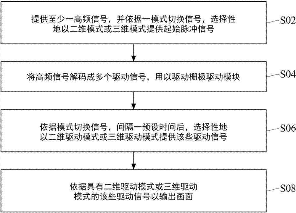
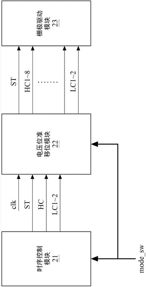
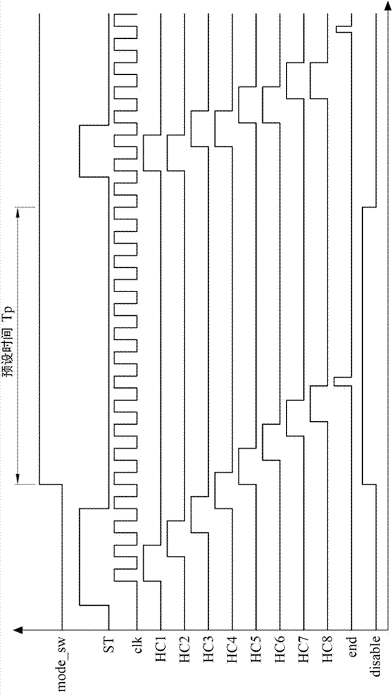
[0033] Please also refer to figure 1 and figure 2 , figure 1 is a flowchart of a method for switching display modes according to an embodiment of the present invention, figure 2 It is a functional block diagram of a display device according to an embodiment of the present invention. As shown in the figure, the display device of this embodiment has a timing control module 21 , a voltage level shift module 22 and a gate driving module 23 . In step S02 , in addition to providing the high-frequency signal HC and the low-frequency signal LC, the timing control module 21 also selectively provides the start pulse signal ST in a two-dimensional mode or a three-dimensional mode according to the mode switching signal mode_sw. In practice, when the externally input mode switch signal mode_sw instructs the timing control module 21 to switch from the 2D mode to the 3D mode, the timing control module 21 will provide a start pulse signal ST with a shorter pulse width.

[0034] In step ...


PUM


Abstract

The invention discloses a display device and a method for switching display modes. In the method, firstly providing at least one high-frequency signal; selectively providing a starting pulse signal in a two-dimensional or three-dimensional mode according to a mode switching signal; then decoding the high-frequency signal into a plurality of driving signals; according to the mode switching signal, after presetting a time at intervals, selectively providing the plurality of driving signals in a two-dimensional or three-dimensional driving mode; outputting a picture according to the plurality signals with the two-dimensional or three-dimensional driving mode. Thus, when the display device switches a two-dimensional or three-dimensional image, a grid driving module is prevented from being damaged due to heavy current leakage as a sequential control module and a voltage level shifting module are out of sync.

Description

technical field [0001] The present invention relates to a display device and a method for switching display modes, in particular to a display device and a method for switching display modes that prevent a gate drive module from leaking a large current. Background technique [0002] At present, many display devices have the function of switching two-dimensional and three-dimensional images, so that users can use various application devices more conveniently. However, when the timing control module (Tcon) and the voltage level shifter module (level shifter) receive the conversion from 2D display to 3D display (that is, 2D to 3D), due to the different designs of various brands, the timing control module And the voltage level shift module may not receive the 2D to 3D conversion command synchronously. For example, in one example, when the timing control module first receives the 2D to 3D conversion command and has changed the pulse width of the initial pulse signal, if the volta...

Claims


Application Information

Patent Timeline
Patent Type & Authority Applications(China)
IPC IPC(8): G09G3/20
Inventor 刘家维李岳翰刘正雄董哲维
Owner AU OPTRONICS CORP
Why Eureka
Try Eureka