Rotary table braking device

A technology of rotary table and brake ring, which is used in manufacturing tools, metal processing equipment, metal processing machinery parts, etc., can solve the problems of worm gear shaft wear, inconvenient maintenance and adjustment, and increased maintenance frequency, and achieves convenient disassembly and adjustment. , Excellent indexing accuracy, the effect of reducing rigidity requirements

Inactive Publication Date: 2017-02-22
SHENJI GRP KUNMING MACHINE TOOL
View PDF8 Cites 0 Cited by
  • Summary
  • Abstract
  • Description
  • Claims
  • Application Information

AI Technical Summary

Problems solved by technology

[0004] The first type of braking mechanism has high rigidity requirements for the main shaft of the worktable or the worm gear shaft. The centering effect of the center of the workbench) or the worm gear shaft has a certain degree of wear and tear, and the frequency of maintenance increases after long-term use, and the entire unit needs to be disassembled during maintenance, which is inconvenient for maintenance and adjustment
At the same time, the space size inside the turntable mechanism is increased, and the rigidity of the turntable and the sliding seat is reduced.
[0005] The second type of braking mechanism has high requirements for the clearance between the worm wheel and the worm, which will especially increase the wear of the copper worm wheel, and requires a relatively large stall torque of the motor connected to the worm
Increasing the motor stall torque by increasing the motor size will increase the cost
[0006] The third type of braking mechanism is realized by directly braking the turntable, which has high requirements on the casting material and processing of the turntable. After a long period of use, the wear of the turntable is too large to be repaired, and the turntable needs to be replaced, which increases the cost.

Method used


Image

  • Rotary table braking device
  • Rotary table braking device
  • Rotary table braking device

Examples


Embodiment Construction

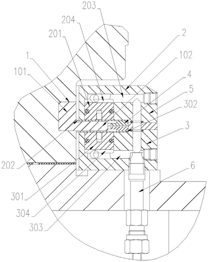
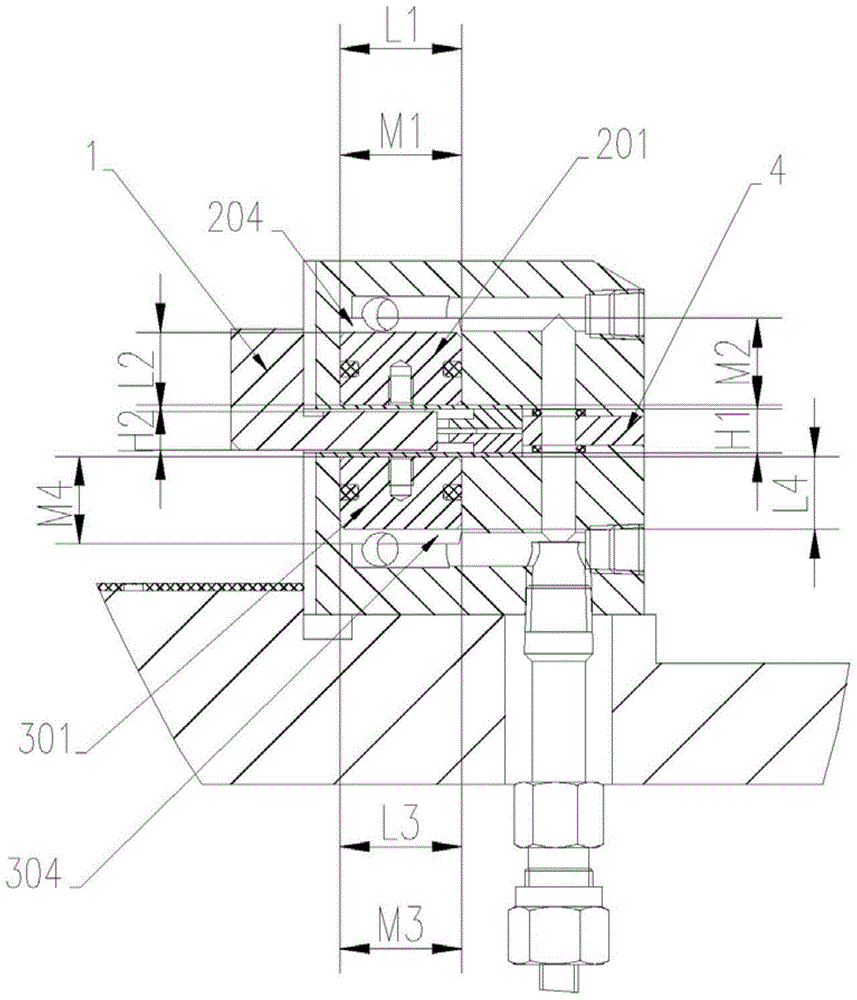
[0026] Such as figure 1 As shown, the braking device of the rotary table according to one embodiment of the present invention includes a braking ring 1 , an upper pressing plate 2 and a lower pressing plate 3 . The upper pressing plate 2 and the lower pressing plate 3 are arranged oppositely, and there is a gap between them. The cross section of the brake ring 1 is "L" shape, the vertical end 101 of the brake ring 1 is fixedly connected with the rotary table, the horizontal end 102 of the brake ring 1 enters the gap between the upper platen 2 and the lower platen 3, and the brake The tight ring 1 rotates synchronously with the rotary table.

[0027] The bottom of the upper platen 2 has an inwardly recessed upper platen piston groove 204 . The upper pressing plate spring piece 202 is fixed on the bottom of the upper pressing plate 2 , and the upper pressing plate spring piece 202 closes the opening of the upper pressing plate piston groove 204 . The upper platen piston 201 i...


PUM


Abstract

The invention discloses a tight braking device of a rotating workbench. The device is characterized by comprising upper press plates and lower press plates, wherein the upper press plates and the lower press plates are oppositely arranged, and tight braking rings are arranged in gaps between the upper press plates and the lower pressing plates. Each upper press plate comprises an upper press plate elastic device and an upper press plate pushing device, the upper press plate elastic device is arranged on the bottom face of the upper press plate, and the upper press plate pushing device can push the upper press plate elastic device to deform. Each lower press plate comprises a lower press plate elastic device and a lower press plate pushing device, the lower press plate elastic device is arranged on the top face of the lower press plate, and the lower press plate pushing device can push the lower press plate elastic device to deform. The upper elastic devices and the lower elastic devices are simultaneously pushed by the upper pushing devices and the lower pushing devices, pressing devices of the tight braking device are arranged between the upper elastic devices and the lower elastic devices, the tight braking rings fixedly connected with a rotary table of the workbench have no influences on rotating accuracy of the workbench, and the rigid requirement for the workbench is also lowered. The tight braking device of the rotating workbench is convenient to detach and adjust, long in service life and low in cost.

Description

technical field [0001] The invention relates to the field of mechanical processing, in particular to a braking device for a high-precision rotary workbench. Background technique [0002] When the CNC rotary table is loaded and rotated, the turntable bears a large rotational inertia. In order to stop the turntable from rotating and ensure excellent precision indexing, it is necessary to have a perfect brake device. [0003] At present, the common braking methods are: by braking the main shaft of the workbench or the worm gear shaft, adding a mechanical tightening, hydraulic or pneumatic tightening mechanism to the outer circle of the main shaft of the worktable and the worm gear shaft; directly braking the worm; turntable. [0004] The first type of braking mechanism has high rigidity requirements for the main shaft of the worktable or the worm gear shaft. The centering effect of the center of the workbench) or the worm gear shaft has a certain wear and tear, and the mainte...

Claims


Application Information

Patent Timeline
Patent Type & Authority Patents(China)
IPC IPC(8): B23Q1/28
CPCB23Q16/06
Inventor 李绍萍徐建平彭梁锋王全宝孙薇朱祥赵建华尹作升
Owner SHENJI GRP KUNMING MACHINE TOOL
Why Eureka
Try Eureka