Lifting mechanism

A lifting mechanism and sliding block technology, applied in the field of lifting mechanism, can solve the problems of limited space, high cost, high price, etc., and achieve the effect of simple structure

Inactive Publication Date: 2014-11-05
BEI OPTICS TECHNOLOGY COMPANY LIMITED
View PDF5 Cites 2 Cited by
  • Summary
  • Abstract
  • Description
  • Claims
  • Application Information

AI Technical Summary

Problems solved by technology

However, the manipulator is specific and expensive. For applications that only measure a few samples each time (such as laboratory measurement), the cost is too high; at the same time, for the selected relatively closed measurement device, due to space Limited, manual loading is difficult to implement directly

Method used


Image

  • Lifting mechanism

Examples


Embodiment Construction

[0008] In order to deeply understand the present invention, the present invention will be described in detail below in conjunction with the accompanying drawings and specific embodiments.

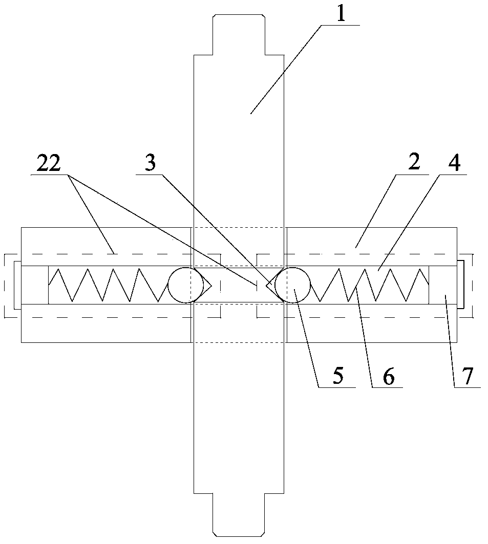
[0009] See attached figure 1 The lifting mechanism provided by the present invention includes a limit shaft 1, a slider 2 and at least two sets of positioning components 22. The slider 2 is sleeved on the limit shaft 1, and the positioning component 22 is arranged on the slider 2. There are multiple positioning intervals 3 in the vertical direction (only one positioning interval is drawn in this embodiment, in practice, multiple positioning intervals can be provided along the axial direction of the limit shaft 1), and the positioning assembly 22 can be snapped on The positioning section 3 enables the position of the slider 2 to be fixed after the lifting.

[0010] Wherein, as a specific implementation of the positioning section 3, the positioning section 3 can be a conical notch indented t...


PUM


Abstract

The invention discloses a lifting mechanism, and belongs to the technical field of sample loading and unloading. The lifting mechanism comprises a limiting shaft, sliding blocks and at least two sets of positioning components. The sliding blocks are sleeved with the limiting shaft, the positioning components are arranged in the sliding blocks, positioning sections are arranged on the limiting shaft in the vertical direction, the positioning components can be buckled in the positioning sections, and therefore the positions, obtained after the sliding blocks ascend and descend, of the sliding blocks can be fixed. The lifting mechanism is simple in structure, the lifting movement of the lifting mechanism on the limiting shaft can be achieved by means of the sliding blocks, and according to the lifting mechanism, the positions, obtained after the sliding blocks ascend and descend, of the sliding blocks can be fixed by means of cooperation of the positioning sections and the positioning components.

Description

technical field [0001] The invention relates to the technical field of devices for loading and unloading samples, in particular to a lifting mechanism. Background technique [0002] Accurately measuring surface information such as the critical dimension, spatial morphology and material properties of a three-dimensional structure formed by a single-layer or multi-layer thin film on a wafer sample plays a very important role in the semiconductor industry. Usually, the surface information of the silicon wafer sample can be obtained by using the optical measurement technology to measure the light signal reflected by the silicon wafer sample non-contact. [0003] Before measuring a wafer sample, it is often necessary to load the sample into a relatively airtight measurement device (such as an ellipsometer). In general, the use of manipulators to load and unload samples can lay the foundation for accurate, safe and efficient measurements. However, the manipulator is specific and...

Claims


Application Information

Patent Timeline
Patent Type & Authority Applications(China)
IPC IPC(8): B65G47/74
Inventor 吴文镜李成敏
Owner BEI OPTICS TECHNOLOGY COMPANY LIMITED
Why Eureka
Try Eureka