Gas boiler burner
A gas-fired boiler and burner technology, applied in burners, gas fuel burners, combustion methods, etc., can solve the problems of high flame port temperature, short service life, insufficient combustion, etc., and achieve high combustion calorific value and high temperature. , The effect of stable and sufficient combustion
- Summary
- Abstract
- Description
- Claims
- Application Information
AI Technical Summary
Problems solved by technology
Method used
Image
Examples
Embodiment 1
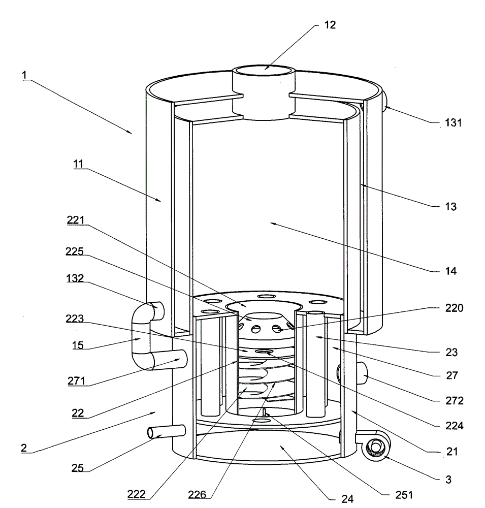
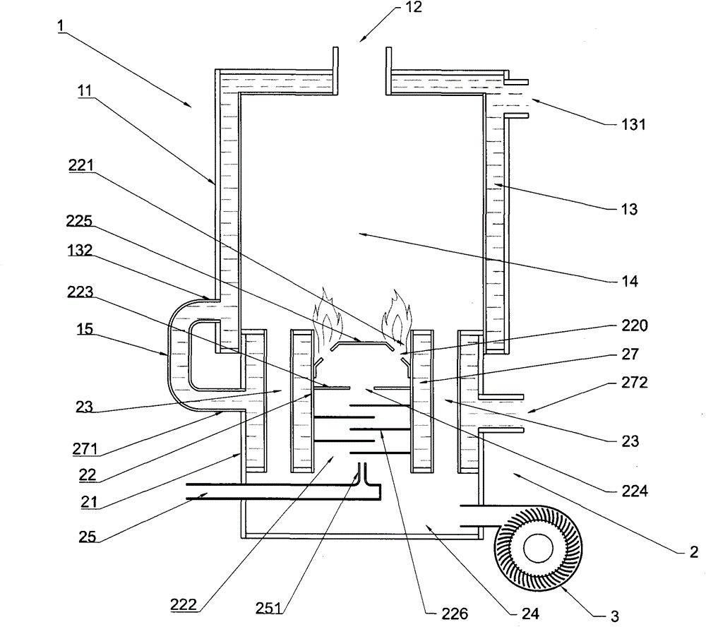
[0036] like figure 1 and figure 2 As shown, a gas boiler burner according to the present invention includes a boiler body 1 and a burner body 2, and the two components are arranged in cooperation to form the main structure of the present invention.
[0037] The boiler body 1 includes a boiler shell 11 , a heating cavity 14 is formed in the boiler shell 11 , and a discharge port 12 is provided on the boiler shell 11 , and the discharge port 12 communicates with the heating cavity 14 . In addition, the boiler shell 11 is provided with a first jacket 13, the first jacket 13 is provided with a first water inlet 131 and a first water outlet 132, the first water inlet 131 and the first outlet The nozzles 132 are in airtight communication with the first jacket 13 .
[0038] The burner body 2 includes a burner casing 21 , a cylinder body 22 is arranged on the inner and upper part of the burner casing 21 , a first mixing chamber 24 is formed in the inner and lower part of the burner...
Embodiment 2
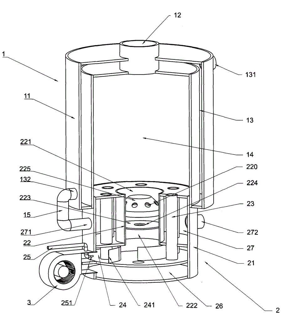
[0045] like image 3 and Figure 4 As shown, an air pressurizing chamber 26 is provided below the first mixing chamber 24 in the present invention, the air pressurizing chamber 26 communicates with the air pressurizing device 3 , and the lower end of the air passage 23 communicates with the air pressurizing chamber 26 . Specifically for this embodiment, the first mixing chamber 24 and the air pressurizing chamber 26 become independent chambers, the air pressurizing chamber 26 provides air for the air passage 23 alone, and the first mixing chamber 24 becomes an independent chamber. At this time, the second mixing chamber 222 can be reserved or omitted. When omitted, the pressure-relief baffle 223 is arranged at the lower port of the cylinder 22, that is, the upper and lower sides of the pressure-relief baffle 223 are the combustion chamber 221 and the first A mixing chamber 24, if the air flux in the cylinder 22 needs to be the maximum amount, the pressure-relief baffle 223 is...
Embodiment 3
[0048] like Figure 5 and Image 6 As shown, a plurality of cylindrical bodies 22 are arranged in parallel in the combustor casing 21 of the present invention. Specifically, in this embodiment, the plurality of cylinders 22 are evenly distributed in the burner housing 21 , each cylinder 22 is provided with a plurality of air passages 23 on the periphery, and the second jacket 27 surrounds all the cylinders 22 ; Each cylinder 22 is provided with a combustion chamber 222 , a combustion plate 225 , a pressure reducing baffle 223 , a second mixing chamber 222 , and a second spoiler 226 as in the first embodiment. The arrangement of the plurality of cylinders 22 in this embodiment enables the burner to output relatively balanced heat on a larger section, and the gas pipeline of each cylinder 22 can also be controlled according to the requirement of combustion heat.
[0049] The implementations and principles of other parts of this embodiment are the same as those of the first and...
PUM
 Abstract
Description
Claims
Application Information
 - R&D
- Intellectual Property
- Life Sciences
- Materials
- Tech Scout
- Unparalleled Data Quality
- Higher Quality Content
- 60% Fewer Hallucinations
Browse by: Latest US Patents, China's latest patents, Technical Efficacy Thesaurus, Application Domain, Technology Topic, Popular Technical Reports.
© 2025 PatSnap. All rights reserved.Legal|Privacy policy|Modern Slavery Act Transparency Statement|Sitemap|About US| Contact US: help@patsnap.com


