A pumpless thermal injection refrigeration cycle method and device

A refrigeration cycle and thermal injection technology, applied in refrigeration and liquefaction, refrigerators, refrigeration components, etc., can solve the problems of reducing system COP, the influence of condensation pressure, and the underutilization of high-temperature and high-pressure refrigerant vapor energy.

Inactive Publication Date: 2016-04-27
ZHEJIANG UNIV
View PDF4 Cites 0 Cited by
  • Summary
  • Abstract
  • Description
  • Claims
  • Application Information

AI Technical Summary

Problems solved by technology

[0007] However, in the above two systems, in order to meet the pressure of the next cycle of liquid storage, when the liquid storage tank is completed as a liquid working fluid, the residual high-temperature and high-pressure refrigerant vapor enters the condenser without being used to condense into a low-pressure liquid On the one hand, the energy of the high-temperature and high-pressure refrigerant vapor is not fully utilized, which reduces the COP of the system; on the other hand, the high-temperature and high-pressure refrigerant vapor affects the condensation pressure

Method used


Image

  • A pumpless thermal injection refrigeration cycle method and device
  • A pumpless thermal injection refrigeration cycle method and device

Examples


Embodiment 1

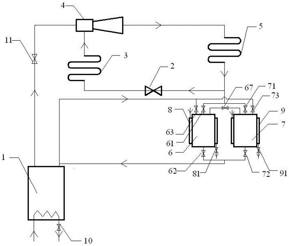
[0062] Such as figure 1 As shown, the pumpless jet refrigeration cycle device of this embodiment adopts tetrachloroethane (R134a) as the circulating working medium, and specifically includes a generator 1, an expansion valve 2, an evaporator 3, an ejector 4, a condenser 5 and a liquid storage The liquid storage device includes a first liquid storage tank 6 and a second liquid storage tank 7 connected in parallel with each other, and each liquid storage tank has the following interfaces respectively, and each interface has a control valve:

[0063] The liquid phase inlet communicates with the outlet of the condenser 5 through the liquid phase inlet control valve 61 of the first liquid storage tank 6 and the liquid phase inlet control valve 71 of the second liquid storage tank 7 respectively;

[0064] The liquid phase outlet communicates with the liquid phase inlet of the generator 1 through the liquid phase outlet control valve 62 of the first liquid storage tank 6 and the liqu...

Embodiment 2

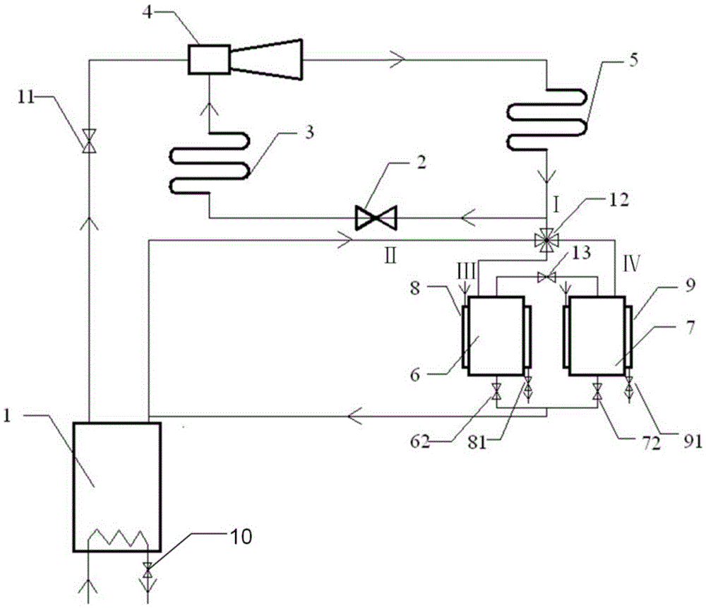
[0078] Such as figure 2 As shown, the outlet of the condenser 5, the vapor outlet of the generator 1, and the gas phase inlets of the two liquid storage tanks are connected through a four-way valve 12 (switching valve), and the two liquid storage tanks are connected through a control valve 13. Other structures are with embodiment 1.

[0079] The workflow of working medium in the present embodiment is as follows:

[0080] Refrigeration stage t 1 , the energy input control valve 10 of the generator 1, the inlet control valve 11 of the injector 4 are opened, the liquid phase outlet control valve 62 and the control valve 72 of the two storage tanks, the control valve 81 and the control valve 91 of the two cooling jackets are all closed, and the four-way valve 12 Connect the I-IV road, the refrigeration system is running, and part of the condensate flowing out of the condenser 5 flows into the second liquid storage tank 7 as a liquid working medium.

[0081] Non-cooling stage t...


PUM


Abstract

The invention discloses a method and device for a pumpless thermal injection refrigeration cycle. The high-temperature and high-pressure refrigerant vapor generated by a generator is used to pressurize the liquid working medium and complete the delivery, and then carry out the liquid working medium to be transported in the next cycle. Pre-pressurization makes full use of the energy of high-temperature and high-pressure refrigerant vapor and improves the COP of the system. The device includes a generator, a throttling element, an evaporator, an ejector, a condenser, and a liquid storage device. The liquid storage device is at least two parallel matched liquid storage tanks, and each liquid storage tank is connected to the generator through a control valve. , the condenser and other matching liquid storage tanks are connected; the ejector is connected in series with the condenser, the throttling element and the evaporator to form a circuit, and the condenser is connected in series with the liquid storage device and the generator to form a circuit. The device makes the energy utilization of the system more economical and reasonable, and reduces the heat load of the cooling water; realizes the system's pump-free circulation, reduces moving parts, and has more stable and reliable operating performance.

Description

technical field [0001] The invention belongs to the technical field of refrigeration, and in particular relates to a pumpless thermal injection refrigeration cycle method and a device for realizing the method. Background technique [0002] The refrigeration industry is a major energy-consuming industry, and the research on refrigeration technology should reduce energy consumption on the basis of ensuring the required cooling capacity. At present, at least half of the heat in industrial production is directly discharged into the atmosphere in various forms of waste heat. These discharged and unused heat not only increase the production cost of the enterprise, cause energy waste, but also cause serious damage to the environment. pollute. [0003] Thermal jet refrigeration technology is a refrigeration technology directly driven by thermal energy. It can use low-grade energy such as waste heat, solar energy, and geothermal energy as driving energy. It not only improves the eff...

Claims


Application Information

Patent Timeline
Patent Type & Authority Patents(China)
IPC IPC(8): F25B41/00F25B41/04F25B49/00F25B41/20F25B41/40
Inventor 何一坚张胜张吉李炜恒李佳碧陈光明
Owner ZHEJIANG UNIV
Why Eureka
Try Eureka