Fireproof cable sleeve

A technology for fireproof casing and cable, applied in electrical components and other directions, can solve the problems of inability to prevent and protect cable fire, time-consuming, power cable fire and burn, etc., to improve the safety performance of electricity consumption, reduce the risk of fire, shorten the The effect of response time

Active Publication Date: 2014-11-05
STATE GRID CORP OF CHINA +1
View PDF6 Cites 14 Cited by
  • Summary
  • Abstract
  • Description
  • Claims
  • Application Information

AI Technical Summary

Problems solved by technology

[0002] At present, in the laying of multiple cables such as power cables and communication cables, it is often necessary to gather multiple cables together for dense laying, or to embed power cables, etc. In environments such as electrical rooms, multiple power cables often need to be closely arranged in a small space where the cables are enough, or the power cables are covered with a layer of PVC casing, and the casing lacks high temperature resistance. and fire extinguishing and alarm capabilities, so when a fire breaks out or a certain cable fails and catches fire anyway, because the power cables are densely arranged or embedded in buildings and other objects, it is impossible to find fire hazards in the first place, let alone in The fire point is dealt with at the first time. Therefore, it is very easy to cause a large area of ​​power cables to catch fire and burn, and it is easy to cause electric shock accidents. A large waste of resources, and more manpower and material resources need to be invested in post-disaster recovery and time-consuming teaching. Therefore, the current power cable arrangement equipment cannot effectively prevent and protect cable fires, and provide safe electricity and power lines. Construction and operation safety pose a serious security threat

Method used


Image

  • Fireproof cable sleeve
  • Fireproof cable sleeve

Examples


Embodiment Construction

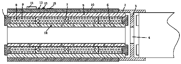
[0013] Such as figure 1 and 2 As shown, a fireproof casing for cables is composed of a wire protection sleeve, a connecting sleeve, a sealing plug 1 and a wire breakage alarm system. The wire protection sleeve is composed of at least two wire-passing pipes, and It is connected through a connecting sleeve. The connecting sleeve is composed of a pipe wall 2 and a baffle 3, wherein the pipe wall 2 and the baffle 3 are of an integrated structure and the axial section is "H" type, and the baffle 3 is additionally provided with The wire hole 4, the wire passing pipe is a hollow tubular structure, the pipe wall is composed of an insulating outer wall 5 and a hot-melt inner wall 6, wherein the distance between the insulating outer wall 5 and the hot-melt inner wall 6 is not less than 1 cm, and is composed of The ribs 7 are connected to form a fireproof cavity 8, the fireproof cavity 8 is distributed parallel to the axial direction of the wire passing pipe, the fire extinguishing cha...


PUM


Abstract

The invention discloses a fireproof cable sleeve. The fireproof cable sleeve is composed of a cable bushing, a connection sleeve, a sealing plug and a broken cable alarming system. The cable bushing is composed of at least two sections of cable passing pipes which are connected through the connection sleeve. The connection sleeve is composed of a pipe wall and a baffle, the cable passing pipes are of a hollow tubular structure, the pipe wall is composed of an outer insulation wall and an inner hot melting wall, and the outer insulation wall and the inner hot melting wall are connected through rib plates to form a fireproof cavity. The broken cable alarming system is composed of a power source, a switch, a buzzer, an early warning wire and an adjusting resistor, and the early warning wire is embedded into the inner hot melting wall and surrounds the inner hot melting wall. On one hand, the cable ignition accident can be effectively eliminated in time and an alarm is given out in time, so that the risk that a cable triggers a fire is reduced greatly; on the other hand, the situation that after one cable breaks down and causes a fire, adjacent cables are damaged is effectively and completely eradicated, the fire damage is reduced greatly, the restoration cost needed after a disaster happens is saved largely, the restoration time spent after a disaster happens is shortened, and the efficiency for eliminating the fire accident is improved.

Description

technical field [0001] The invention relates to a cable fireproof casing, which belongs to the field of protective equipment for laying electric cables. Background technique [0002] At present, in the laying of multiple cables such as power cables and communication cables, it is often necessary to gather multiple cables together for dense laying, or to embed power cables, etc. In environments such as electrical rooms, multiple power cables often need to be closely arranged in a small space where the cables are enough, or the power cables are covered with a layer of PVC casing, and the casing lacks high temperature resistance. and fire extinguishing and alarm capabilities, so when a fire breaks out or a certain cable fails and catches fire anyway, because the power cables are densely arranged or embedded in buildings and other objects, it is impossible to find fire hazards in the first place, let alone in The fire point is dealt with at the first time. Therefore, it is very...

Claims


Application Information

Patent Timeline
Patent Type & Authority Applications(China)
IPC IPC(8): H02G3/04
Inventor 薛双勋蔡战清
Owner STATE GRID CORP OF CHINA
Why Eureka
Try Eureka