Low-noise voltage-controlled oscillator biasing circuit and frequency source self-calibration method

A technology of voltage-controlled oscillators and bias circuits, applied in power oscillators, electrical components, etc., can solve the problems of increasing circuit costs, high noise of voltage dividing circuits, and increasing the output pins of bias circuits, etc., to reduce the number of pins , the output noise is small, and the effect of avoiding changes

Active Publication Date: 2014-11-05
CHENGDU CORPRO TECH CO LTD
View PDF7 Cites 7 Cited by
  • Summary
  • Abstract
  • Description
  • Claims
  • Application Information

AI Technical Summary

Problems solved by technology

[0003] like image 3 As shown, the traditional bias circuit generally divides the voltage by resistors, but because the noise of the voltage divider circuit composed of series resistors R4 and R5 is relatively large, it is necessary to add a large capacitor outside the bias circuit ( image 3 Capacitor C4) in the filter, which increases the output pin of the bias circuit and increases the circuit cost

Method used


Image

  • Low-noise voltage-controlled oscillator biasing circuit and frequency source self-calibration method
  • Low-noise voltage-controlled oscillator biasing circuit and frequency source self-calibration method
  • Low-noise voltage-controlled oscillator biasing circuit and frequency source self-calibration method

Examples


Embodiment Construction

[0023] The technical solution of the present invention will be further described in detail below in conjunction with the accompanying drawings, but the protection scope of the present invention is not limited to the following description.

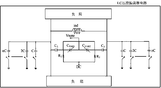
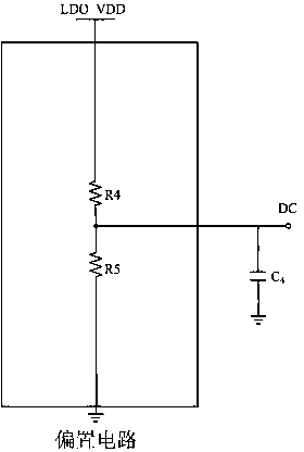
[0024] Such as Figure 4 As shown, the low-noise voltage-controlled oscillator bias circuit is used in conjunction with the LC voltage-controlled oscillator to provide a voltage bias point for the LC voltage-controlled oscillator in the frequency source circuit. It consists of a constant voltage source LDO_VDD, a voltage divider circuit and Composed of filter capacitor C1, the voltage divider circuit includes a high-value poly resistor R1, a first bipolar junction transistor BJT1 and a second bipolar junction transistor BJT2 connected in series, and a high-value poly resistor R1 is connected in series with a BJT tube. The voltage divider circuit divides the voltage output by the LDO. The high value poly resistor R1 is connected to the coll...


PUM


Abstract

The invention discloses a low-noise voltage-controlled oscillator biasing circuit and a frequency source self-calibration method. A voltage division circuit comprises a resistor R1, a first bipolar junction transistor BJT1 and a second bipolar junction transistor BJT2 which are connected in series in sequence, wherein the R1 is connected with the collector of the BJT1; the emitter of the BJT1 is connected with the collector of the BJT2; the collector of the BJT1 is connected with the base of the BJT1; and the collector of the BJT2 is connected with the base of the BJT2. In a self-calibration state, voltage output by the biasing circuit is connected with the tuning voltage input end and the power supply end of an LC voltage-controlled oscillator respectively. The output noise of the biasing circuit disclosed by the invention is low, a filter capacitor does not need to be added externally, the pins of a chip can be effectively reduced, and the cost is reduced; and when a frequency source is in the self-calibration state, the voltage output by the biasing circuit is connected with the tuning voltage input end and the power supply end of the LC voltage-controlled oscillator respectively, so that influences caused by the change of an output DC (Direct-Current) point due to changes of the resistor and the BJTs in a whole temperature range can be effectively eliminated, and change of the frequency source along with temperature change in the self-calibration state is avoided.

Description

technical field [0001] The invention relates to a low-noise voltage-controlled oscillator bias circuit and a frequency source calibration method. Background technique [0002] At present, the frequency source circuit uses an LC voltage-controlled oscillator, and its structure is as follows figure 1 As shown, it is mainly composed of negative resistance, inductance and capacitance, and its output power is: Among them, L is an inductor, C is a capacitor, and the capacitor C is composed of three parts: a parasitic capacitor, a variable capacitor, and a programmable capacitor array. The function of capacitor C2 and capacitor C3 is to block the direct current, and give the LC voltage-controlled oscillator a DC point through other bias circuits, so that the capacitance value of the variable capacitor follows the voltage at both ends of the LC voltage-controlled oscillator (power supply terminal DC and tuning The change of the voltage difference at the voltage input terminal Vtu...

Claims


Application Information

Patent Timeline
Patent Type & Authority Applications(China)
IPC IPC(8): H03B5/32
Inventor 李旺
Owner CHENGDU CORPRO TECH CO LTD
Why Eureka
Try Eureka