Noise separation method based on optical transmission-reception system of fiber sensor

An optical fiber sensor and noise separation technology, applied in the direction of using optical devices to transmit sensing components, can solve problems such as limited performance, randomness, non-reciprocity errors, and inability to separate sub-module noise, and achieve the effect of improving system performance.

Active Publication Date: 2015-09-23
BEIHANG UNIV
View PDF4 Cites 7 Cited by
  • Summary
  • Abstract
  • Description
  • Claims
  • Application Information

AI Technical Summary

Problems solved by technology

Optical fiber sensor is a kind of precision sensing device, any randomness and non-reciprocity factors will produce serious errors, greatly limiting the improvement of its performance
[0004] At present, the optical transceiver system noise measurement

Method used


Image

  • Noise separation method based on optical transmission-reception system of fiber sensor
  • Noise separation method based on optical transmission-reception system of fiber sensor
  • Noise separation method based on optical transmission-reception system of fiber sensor

Examples


Embodiment Construction

[0017] The present invention will be further described in detail below in conjunction with the accompanying drawings.

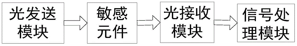
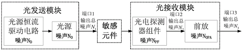
[0018] The invention is a noise separation method based on the optical fiber sensor optical transceiver system, which can measure the noise of each sub-module of the optical fiber sensor optical transceiver system and separate the light source intensity noise. The separation method of the present invention is as Figure 4 As shown, it specifically includes the following steps:

[0019] Step 1: Design the magnetic shielding device.

[0020] To measure the noise of the fiber optic gyroscope optical transceiver system circuit (light source drive circuit, photodetector component and waveguide drive circuit), it is necessary to design the shielding device required for the measurement in advance to eliminate external noise sources, such as Figure 5 Shown: Place the fiber optic sensor optical transceiver module in a magnetically shielded metal (copper, iron, alum...


PUM


Abstract

The invention discloses a noise separation method based on an optical transmission-reception system of a fiber sensor, comprising steps of designing a magnetic shielding device, determining a circuit noise RMS value acquisition method, measuring and adopting the RMS value acquisition method to obtain terminal output overall noise of the optical transmission-reception system of the fiber sensor and a local noise RMS value of a sub-module, determining a noise conversion parameter and separating light source intensity noise N0, and calculating the noise proportion of each module in the overall noise of the optical transmission-reception system of the fiber sensor. When measuring the overall noise, the noise separation method based on the optical transmission-reception system of the fiber sensor can obtain the light source intensity noise of the light source and the noise value of all circuit modules, and can obtain the proportion in the overall noise of the optical transmission-reception system of the fiber sensor.

Description

technical field [0001] The invention relates to a noise separation method based on an optical fiber sensor optical transceiver system, which belongs to the field of noise measurement. Background technique [0002] Optical fiber sensors are devices that sense various physical information (sound, magnetism, temperature, rotation, etc.), and can be used in high voltage, electrical noise, high temperature, corrosion or other harsh environments, such as figure 1 As shown, it is mainly composed of the following parts: optical sending module, used to generate and send optical signals; sensitive components, used to sense various physical information, so as to obtain changes in sound, magnetism, temperature, rotation, etc.; optical receiving module The module is used to receive the modulated optical signal of the measured object and convert the optical signal into an electrical signal; the signal processing module is used to process the electrical signal into the desired measured obj...

Claims


Application Information

Patent Timeline
IPC IPC(8): G01D5/353
Inventor 金靖晏云孔令海腾飞张少博宋镜明
Owner BEIHANG UNIV
Why Eureka
Try Eureka