Wideband low noise sensor amplifier circuit

a sensor amplifier and wideband technology, applied in the direction of amplifiers with tubes, amplifiers with semiconductor devices/discharge tubes, amplifiers with tubes, etc., to achieve the effect of reducing the output noise of the amplifier, and effectively reducing the adverse effect of the sensor stray capacitan

Active Publication Date: 2012-03-29
HITACHI LTD
View PDF2 Cites 7 Cited by
  • Summary
  • Abstract
  • Description
  • Claims
  • Application Information

AI Technical Summary

Benefits of technology

[0010]In order to reduce the adverse effect of the sensor stray capacitance, a negative capacitance circuit is electrically connected in parallel with the sensor output and thus with the input to the amplifier. In one design, the negative capacitance circuit includes an amplifier having its output connected to one lead of a capacitor. The other lead of the capacitor as well as the input to the amplifier is connected in parallel with the sensor output. Consequently, by adjusting the gain of the second amplifier, a negative capacitance is inserted between the sensor and the sensor amplifier which effectively reduces the adverse effects of the stray capacitance of the sensor.
[0011]In practice, the negative capacitance is adjusted to a value less than the value of the stray capacitance and preferably one half the value of the stray capacitance. By doing so, the output noise from the amplifier is reduced while expanding bandwidth for the sensor circuit.

Problems solved by technology

The sensor also exhibits stray capacitance which results from the design of the sensor.

Method used


Image

  • Wideband low noise sensor amplifier circuit
  • Wideband low noise sensor amplifier circuit
  • Wideband low noise sensor amplifier circuit

Examples


Embodiment Construction

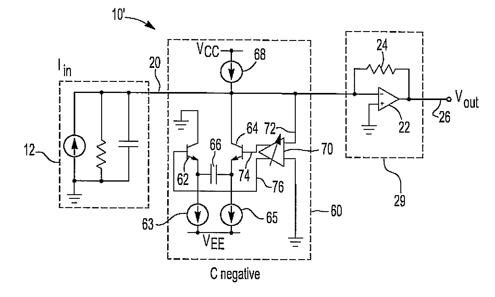
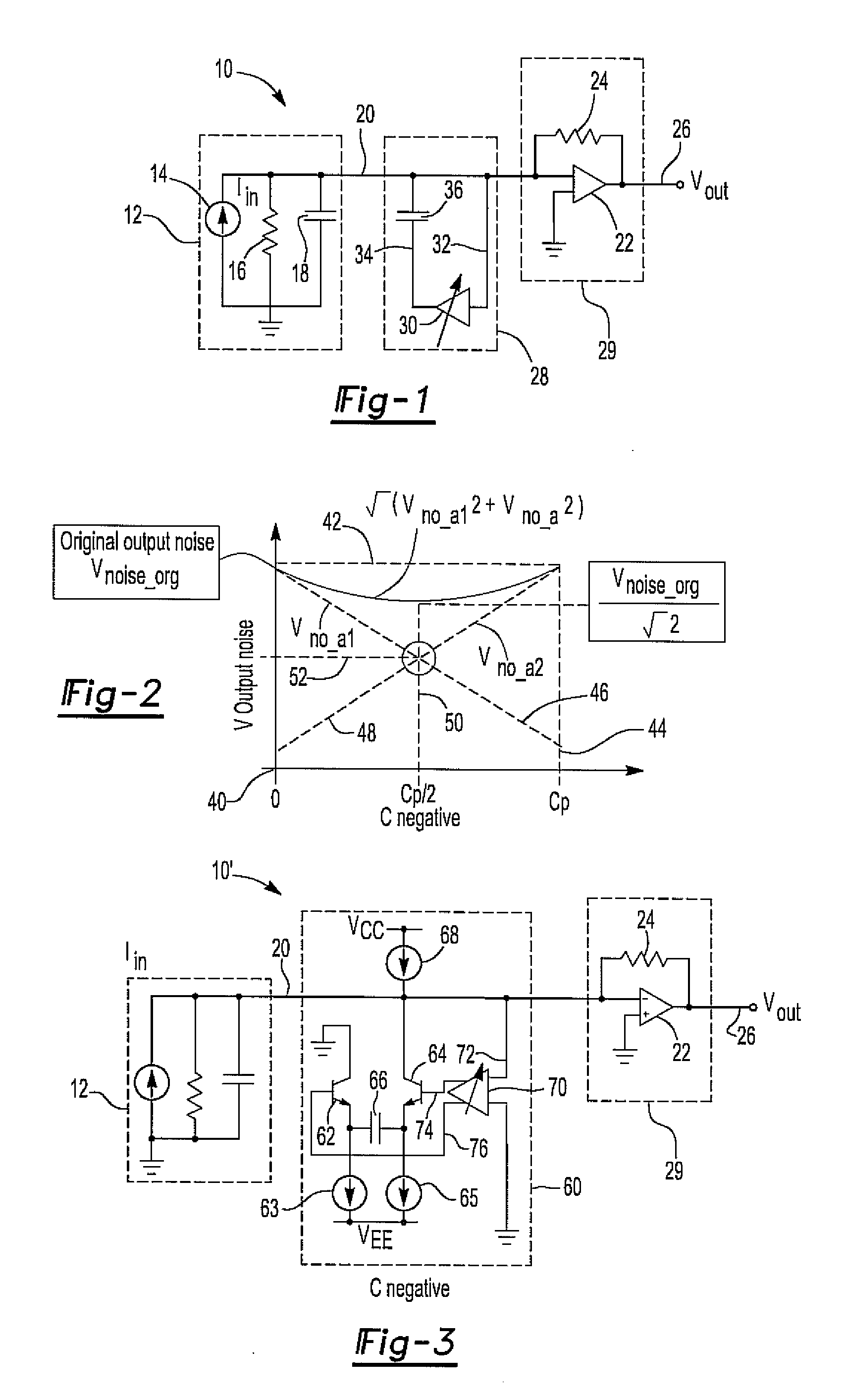
[0016]With reference first to FIG. 1, a first preferred embodiment of a sensor circuit 10 in accordance with the present invention is shown. In the conventional fashion, the sensor circuit 10 includes a sensor 12, such as a photo diode sensor.

[0017]The sensor 12 includes an electric current source 14, whose amount of current generated varies as a function of the intensity of the light in the case of a photo diode sensor. The sensor 12 also includes an output resistance as indicated by resistor 16.

[0018]The sensor 12 exhibits stray capacitance illustrated as a capacitor 18 coupled in parallel with the resistor 16 and the current source 14. This capacitor 18, furthermore, adversely affects the bandwidth and noise level on the output 26 from the sensor circuit 10.

[0019]The sensor output 20 is coupled as an input signal to a high-gain amplifier 22. A feedback resistor 24 controls the trans-impedance of the trans-impedance amplifier 29 so that an output 26 from the amplifier 22 forms the...


PUM


Abstract

A circuit having a sensor with a stray capacitance value. An output from the sensor is connected to the input of an amplifier while a negative capacitance circuit is electrically connected in parallel with the sensor output. The negative capacitance circuit reduces the effect of the sensor stray capacitance to provide an increased bandwidth and decreased noise on the amplifier output.

Description

BACKGROUND OF THE INVENTION[0001]I. Field of the Invention[0002]The present invention relates generally to sensor amplifier circuits.[0003]II. Description of Related Art[0004]During the evaluation, design, and testing of electronic circuits, many types of different sensors are utilized. Especially, electrical / optical sensors, magnetic / optical sensors, and loop antenna current sensors are all useful devices for the development and investigation of electromagnetic capability as well as signal / power integrity for many types of electronics.[0005]These sensors utilize a photo sensor to detect a signal from the device under test. Furthermore, such sensors require both a wideband and low noise amplifier in order to test high frequency circuits with high accuracy.[0006]One disadvantage of these sensors, and particularly photo sensors, is that the sensor exhibits stray capacitance which is coupled to the input of the amplifier. This stray capacitance not only reduces bandwidth of the amplifi...

Claims


Application Information

Patent Timeline
Patent Type & Authority Applications(United States)
IPC IPC(8): H03F1/00
CPCH03F1/08H03F3/45098H03F2203/45458H03F2200/261H03F2200/411H03F2200/213
Inventor TAKAHASHI, MASAYOSHICHUJO, NORIOMAKUUCHI, MASAMI
Owner HITACHI LTD
Why Eureka
Try Eureka