An ultrasonic cavitation device

A cavitation and ultrasonic technology, applied in the field of ultrasonic cavitation, can solve the problems of low efficiency of ultrasonic cavitation devices, and achieve the effect of high space volume ratio and high cavitation intensity

Active Publication Date: 2016-08-31
INST OF ACOUSTICS CHINESE ACAD OF SCI
View PDF8 Cites 0 Cited by
  • Summary
  • Abstract
  • Description
  • Claims
  • Application Information

AI Technical Summary

Problems solved by technology

[0003] The purpose of the present invention is to provide a high-efficiency ultrasonic cavitation device for the problem of low efficiency of the prior art ultrasonic cavitation device

Method used


Image

  • An ultrasonic cavitation device
  • An ultrasonic cavitation device
  • An ultrasonic cavitation device

Examples


Embodiment Construction

[0021] Other characteristics, characteristics and advantages of the present invention will be more apparent after the following detailed description of the embodiments of the present invention by way of examples in conjunction with the accompanying drawings.

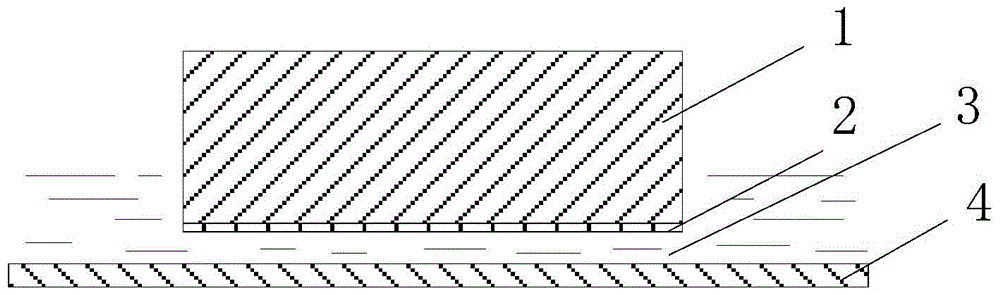
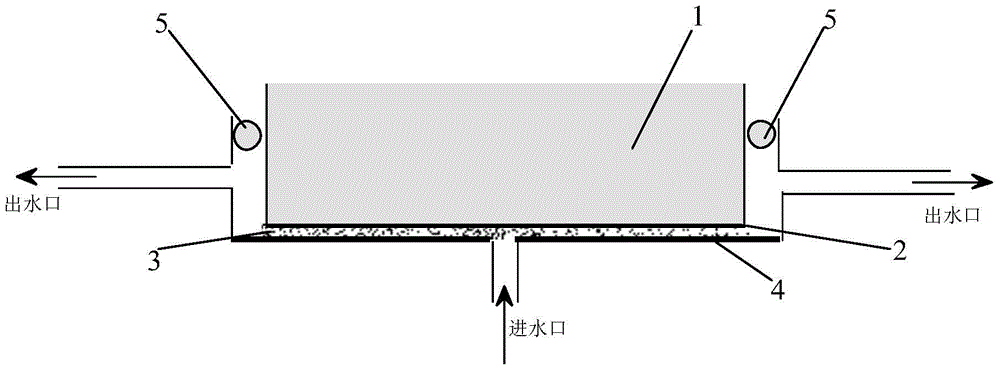
[0022] figure 1 It is a schematic structural diagram of an ultrasonic cavitation device provided by an embodiment of the present invention. Such as figure 1 As shown, the ultrasonic cavitation device includes: a vibrating body 1 and a reflector 4 , wherein the vibrating body 1 has a radiation surface 2 at one end, and a liquid thin layer 3 is formed between the radiation surface 2 and the reflector 4 . The vibration body 1 is used to convert electric energy into ultrasonic waves, and the ultrasonic waves enter into the liquid thin layer 3 through the radiation surface 2 and form an acoustic field in the liquid thin layer 3 .

[0023] The reflector 4 reflects the ultrasonic waves radiated by the radiating surface 2, and...


PUM


Abstract

The invention relates to an ultrasonic cavitation device, which comprises: a vibration body and a reflector, wherein a radiation surface is arranged at one end of the vibration body, and a liquid thin layer is formed between the radiation surface and the reflection body; the vibration body generates ultrasonic waves and enters through the radiation surface into the liquid thin layer, and form a sound field in the liquid thin layer; the reflector reflects the ultrasonic radiation radiated by the radiation surface, and the sound field in the liquid thin layer is strengthened through multiple reflections and superpositions of the reflector and the radiation surface ultrasonic waves, thereby A large cavitation cloud is formed that spreads laterally along a thin layer of liquid. In the ultrasonic cavitation device provided by the present invention, a reflective surface is arranged on the side of the transducer radiation surface, so that under a small input power, the sound field in the liquid thin layer is strengthened to form a large-area laterally spread cavitation cloud.

Description

technical field [0001] The invention relates to the field of ultrasonic cavitation, in particular to an ultrasonic cavitation device. Background technique [0002] Cavitation refers to the formation of cavitation bubbles in the liquid and its subsequent dynamic behavior when the pressure of the liquid drops to a sufficiently low level. Bubbles, these bubbles are generated and collapsed instantly (between a few microseconds to tens of microseconds) according to the cycle of the ultrasonic wave, forming a cloud of bubbles. When these bubbles collapse, high temperature and high pressure will be generated inside the bubbles, and shock waves will be generated in the surrounding liquid. When they are close to the wall, they will move towards the wall and form micro jets hitting the wall. At present, the applications of cavitation, such as ultrasonic cleaning and sonochemistry, are carried out in large water bodies, which not only causes waste of water resources, but also reduces ...

Claims


Application Information

Patent Timeline
Patent Type & Authority Patents(China)
IPC IPC(8): B01J19/10
Inventor 白立新邓京龙李超徐德龙林伟军白丽荣
Owner INST OF ACOUSTICS CHINESE ACAD OF SCI
Why Eureka
Try Eureka