A semi-continuous casting device and method for group frequency ultrasonic magnesium alloy
A magnesium alloy, semi-continuous technology, applied in the direction of casting equipment, casting melt containers, manufacturing tools, etc., can solve the problems of low cavitation intensity, sound pressure attenuation, etc., and achieve the improvement of cavitation intensity, reduction of oxidation, and cavitation The effect of range enhancement
- Summary
- Abstract
- Description
- Claims
- Application Information
AI Technical Summary
Problems solved by technology
Method used
Image
Examples
Embodiment 1
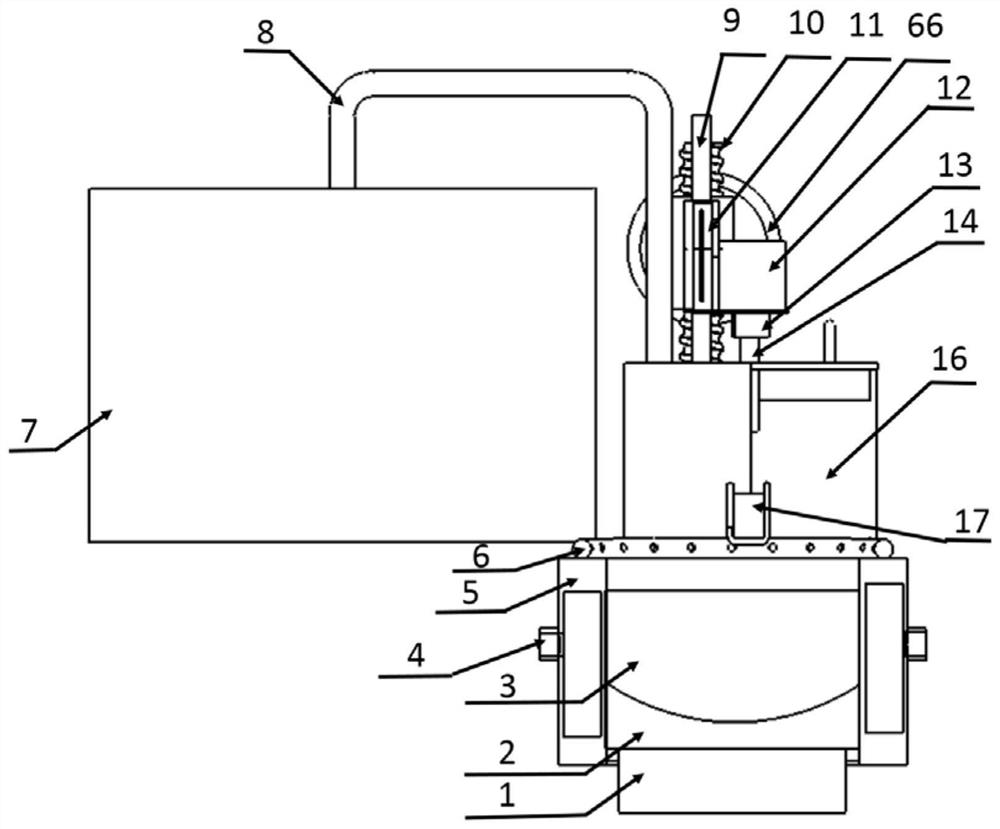
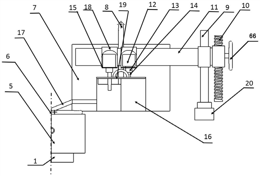
[0070] The structure of the group frequency ultrasonic magnesium alloy semi-continuous casting device is as follows: figure 1 and figure 2 Shown, comprise melting furnace 7, tundish 16 and crystallizer 5, be provided with pipette 8 between smelting furnace 7 and tundish 16, be provided with chute 17 between tundish 16 and crystallizer 5;
[0071] The top of the crystallizer 5 is provided with a protective gas annular pipe 6, and the inside of the protective gas annular pipe 6 is connected with the protective gas source through a pipeline. The protective gas annular pipe 6 is provided with an air outlet, and the air outlet faces the axis of the crystallizer;
[0072] The tundish is provided with a first ultrasonic generating device and a second ultrasonic generating device, the first ultrasonic generating device is composed of a first ultrasonic radiation rod 14, a first ultrasonic guiding rod 13 and a first ultrasonic transducer 12, and the second ultrasonic generating device...
Embodiment 2
[0090] Device structure is the same as embodiment 1, and difference is:
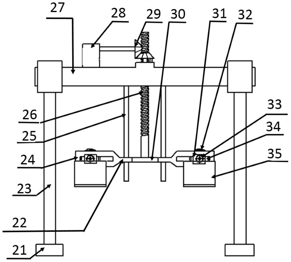
[0091] (1) The support device is a variable-angle support device with a structure such as image 3 and Figure 4 Shown, comprise variable angle supporting device crossbeam 27, guide bar 25, elevating device and angle adjusting device; 26 passes through the crossbeam 27 of the variable angle support device and is threadedly connected with the crossbeam 27 of the variable angle support device, and the bottom of the variable angle support device screw rod 26 is connected with one end of the two connecting rods 22 through the bearing 30; the other end of each connecting rod 22 is fixed There is a strut 24 with a dovetail groove 34, and a horizontal channel is provided in the dovetail groove 34 for the horizontal movement of the wheel shaft; two guide rods 25 respectively pass through a connecting rod 22 and are slidably connected with the connecting rod 22; The supporting device slider 31 is respectively s...
Embodiment 3
[0105] Device structure is the same as embodiment 1, and difference is:
[0106] Ultrasonic transducer structure such as Figure 8 As shown in (b), two sets of titanate piezoelectric ceramic materials are arranged in each transducer box;
[0107] Method is with embodiment 1, and difference is:
[0108] (1) Preparation Magnesium alloy ingot;
[0109] (2) The temperature of the magnesium alloy melt is 50°C above the liquidus line of the magnesium alloy;
[0110] (3) The tundish, the pipette, the first ultrasonic radiation rod and the second ultrasonic radiation rod are preheated to the same temperature as the magnesium alloy melt;
[0111] (4) The frequencies of ultrasonic waves emitted by the first ultrasonic radiation rod and the second ultrasonic radiation rod are 30 kHz and 35 kHz respectively; the bottom ends of the first radiation rod and the second radiation rod are located 30 mm below the liquid surface.
PUM
 Abstract
Description
Claims
Application Information
 - R&D
- Intellectual Property
- Life Sciences
- Materials
- Tech Scout
- Unparalleled Data Quality
- Higher Quality Content
- 60% Fewer Hallucinations
Browse by: Latest US Patents, China's latest patents, Technical Efficacy Thesaurus, Application Domain, Technology Topic, Popular Technical Reports.
© 2025 PatSnap. All rights reserved.Legal|Privacy policy|Modern Slavery Act Transparency Statement|Sitemap|About US| Contact US: help@patsnap.com


