A Strong Shear Annular Jet Cavitation Generator

A technology of annular jets and generators, applied in the direction of chemical/physical/physicochemical nozzle reactors, etc., can solve the problems of poor cavitation effect and weak cavitation intensity, and achieve high cavitation intensity and strong cavitation effect , the effect of easy processing

Active Publication Date: 2021-09-03
WUHAN UNIV
View PDF5 Cites 0 Cited by
  • Summary
  • Abstract
  • Description
  • Claims
  • Application Information

AI Technical Summary

Problems solved by technology

[0003] Venturi tubes, orifice plates, etc. are generally used as cavitation generators at present, but the existing cavitation generators have weak cavitation strength and poor cavitation effect

Method used


Image

  • A Strong Shear Annular Jet Cavitation Generator
  • A Strong Shear Annular Jet Cavitation Generator

Examples


Embodiment Construction

[0018] The present invention will be further described below in conjunction with the embodiments and accompanying drawings.

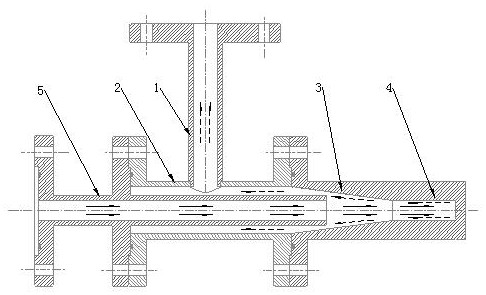
[0019] A strong shear annular jet cavitation generator, comprising a high-pressure water supply pipe 1, an outlet pipe 5 connected coaxially and communicated in sequence, a rectifying pipe 2, a tubular contraction section 3, and a back pressure chamber 4; the high-pressure water supply pipe 1 is in vertical communication with the rectification tube 2; the outer diameter of the outflow tube 5 is smaller than the inner diameter of the rectification tube 2; one end of the back pressure chamber 4 communicates with the constriction section 3, and the other end is closed.

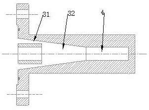
[0020] The tubular contraction section 3 is coaxially connected with the outlet pipe 5, and the inner wall of the contraction section 3 and the periphery of the outlet pipe 5 form a tapered annular cavity, which is an annular nozzle 31. The area ratio of the cross section is 0.25-0.5.

[...


PUM


Abstract

The invention discloses a strong-shear annular jet cavitation generator, which comprises a high-pressure water supply pipe, a rectifier pipe, a tubular constriction section, a back pressure chamber and an outlet pipe, wherein the tubular constriction section can be further divided into an annular nozzle and a cavitation nozzle. room in two parts. The working fluid enters the rectifier pipe through the high-pressure water supply pipe, and then flows through the annular nozzle. After the pressure energy is converted into kinetic energy, it is ejected at a high speed at the outlet of the annular nozzle and injected into the cavitation chamber. Due to the diffusion of the jet and the hindrance of the back pressure chamber, The backflow of the working fluid occurs, and the backflow meets the high-speed jet in the cavitation chamber to generate a strong shearing effect, which induces severe cavitation. Then the cavitation flow flows through the cavitation chamber and the outlet pipe, the flow velocity decreases, the pressure increases, and the cavitation bubbles collapse under the action of higher pressure, resulting in local high temperature and high pressure, and the formation of shock waves and micro jets. The invention can realize strong shearing action, so that the cavitation intensity is higher and the cavitation effect is better. The invention has no moving parts, simple structure, easy processing and can be used on a large scale.

Description

technical field [0001] The invention relates to a hydraulic cavitation generator, in particular to a strong shear annular jet flow cavitation generator. Background technique [0002] Cavitation is the process of forming, developing and collapsing vapor or gas voids inside the liquid or on the liquid-solid interface when the local pressure in the liquid is reduced to the saturated vapor pressure of the liquid. For a long time, people are committed to preventing the occurrence of cavitation and reducing the harm of cavitation. However, the local high temperature, high pressure, powerful shock wave, and high-speed micro-jet generated during the cavitation flow from the initial generation, development to collapse of the cavitation flow can be effectively applied to environmental protection engineering, bioengineering, and food industry, such as sewage Treatment, sterilization and emulsification processing, etc. [0003] Currently, Venturi tubes, orifice plates, etc. are genera...

Claims


Application Information

Patent Timeline
Patent Type & Authority Patents(China)
IPC IPC(8): B01J19/26
CPCB01J19/26
Inventor 龙新平左丹季斌
Owner WUHAN UNIV
Why Eureka
Try Eureka