A kind of cavitation generator with special-shaped flow channel

A technology of generator and annular flow channel, which is applied in the directions of fluid mixers, chemical instruments and methods, chemical/physical processes, etc., can solve the problems of low cavitation efficiency, achieve enhanced turbulent flow intensity, drop water supply pressure, and enhance air flow. effect

Active Publication Date: 2022-01-28
DALIAN MARITIME UNIVERSITY
View PDF16 Cites 0 Cited by
  • Summary
  • Abstract
  • Description
  • Claims
  • Application Information

AI Technical Summary

Problems solved by technology

To sum up, existing cavitation generators often require high incoming pressure and flow velocity to generate sufficient cavitation, and the cavitation efficiency is low at low pressure and low velocity.

Method used


Image

  • A kind of cavitation generator with special-shaped flow channel
  • A kind of cavitation generator with special-shaped flow channel
  • A kind of cavitation generator with special-shaped flow channel

Examples


Embodiment Construction

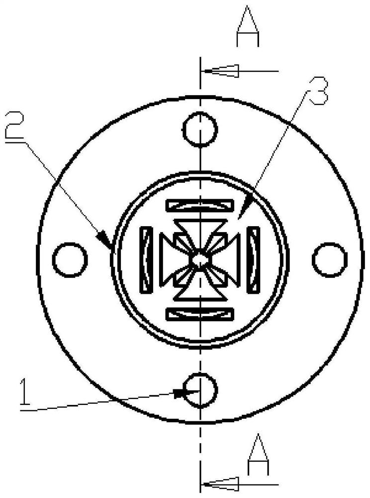
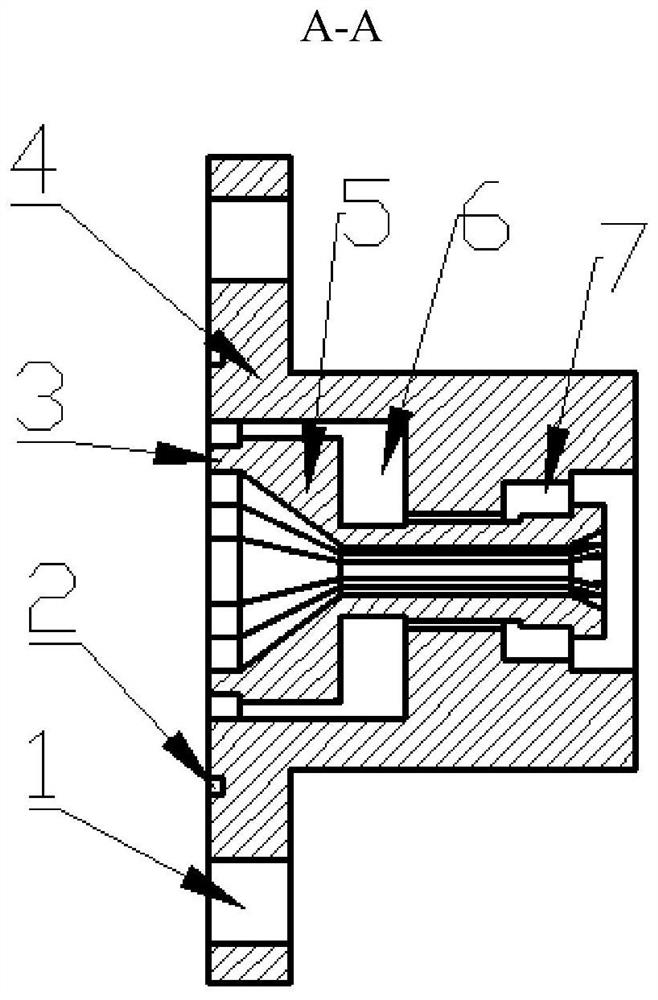
[0031] The technical solutions of the present invention will be further described below in conjunction with the accompanying drawings and through specific implementation methods. Such as Figure 1-9 As shown, a cavitation generator with a special-shaped flow channel includes a connecting block 3, an outer tube 4 and an inner tube 5, and an annular flow channel is formed between the outer tube 4 and the inner tube 5, and the center of the inner tube 5 It is the central flow channel; the outer tube 4 and the inner tube 5 form a whole double flow channel through the connecting block 3, and the whole double flow channel is printed by 3D printing technology;

[0032] The central flow passage is composed of an inlet section, a tapering section, a holding section and a diverging section, and the cross section of the central flow passage is an irregular polygon;

[0033] The annular flow channel is a stepped flow channel in the axial direction and consists of two deceleration chamber...


PUM


Abstract

The invention discloses a cavitation generator with a special-shaped flow channel, which comprises an outer pipe, an inner pipe and a connecting block, the space between the outer pipe and the inner pipe is an annular flow passage, and the center of the inner pipe is a central flow passage; The outer tube and the inner tube form a whole double flow channel through a connecting block, and the whole double flow channel is printed by 3D printing technology; the central flow channel is composed of an inlet section, a tapering section, a holding section and a diverging section Composition, the cross-section of the central channel is an irregular polygon; the annular channel is a stepped channel along the axial direction and consists of two stages of deceleration chambers. The special-shaped flow channel adopted in the present invention can greatly enhance the turbulent flow intensity in the tapered section and the tapered section through exploration. In the tapered section, the fluid will squeeze from the dovetail-shaped part of the flow channel to the square part. Diffuse from the square part of the flow channel to the dovetail part, forming strong turbulence and eddies. The cavitation intensity is significantly enhanced, the required water supply pressure is significantly reduced, and it is more efficient and energy-saving.

Description

technical field [0001] The invention relates to cavitation water jet cleaning, polishing and micromachining technologies, in particular to a cavitation generator with a special-shaped flow channel. Background technique [0002] Where there is a large velocity gradient in the fluid, velocity diffusion occurs in the fluid, resulting in a negative pressure zone. Due to the existence of the negative pressure zone, the dissolved gas nuclei contained in the jet can grow into cavitation bubbles full of steam. Collapse, a large number of cavitation collapses make the water body produce ultrasonic waves and micro jets, and then form a high temperature and high pressure area, and finally make huge energy frequently released in a narrow range, and the shock waves generated can clean the dirt on the surface of the object. To a certain extent, the essence of cavitation is vortex, so enhancing the intensity of turbulence can enhance the intensity of cavitation. [0003] In addition, the...

Claims


Application Information

Patent Timeline
Patent Type & Authority Patents(China)
IPC IPC(8): B01F25/00B01F23/45
CPCB01F23/235B01F2025/916B01F25/00B01F2101/48
Inventor 马文琦孙红镱张京桐
Owner DALIAN MARITIME UNIVERSITY
Why Eureka
Try Eureka