Vacuum clamp for centering optical element in machining process

A technology of optical components and vacuum clips, which is applied in the direction of optical components, optics, manufacturing tools, etc., can solve the problems of chipping and damage of components, and achieve the effect of fast centering and avoiding chipping and damage of components

Inactive Publication Date: 2014-11-12
CHANGCHUN INST OF OPTICS FINE MECHANICS & PHYSICS CHINESE ACAD OF SCI
View PDF4 Cites 11 Cited by
  • Summary
  • Abstract
  • Description
  • Claims
  • Application Information

AI Technical Summary

Problems solved by technology

[0003] The purpose of the present invention is to solve the problem of edge chipping and damage caused by the centering of hammers and dial gauges used in the process of milling and polishing centering of traditional small and ultra-thin optical elements, and to provide a kind of optical element processing Vacuum fixture for centering

Method used


Image

  • Vacuum clamp for centering optical element in machining process
  • Vacuum clamp for centering optical element in machining process
  • Vacuum clamp for centering optical element in machining process

Examples


Embodiment Construction

[0019] The present invention will be described in further detail below in conjunction with the accompanying drawings and specific embodiments.

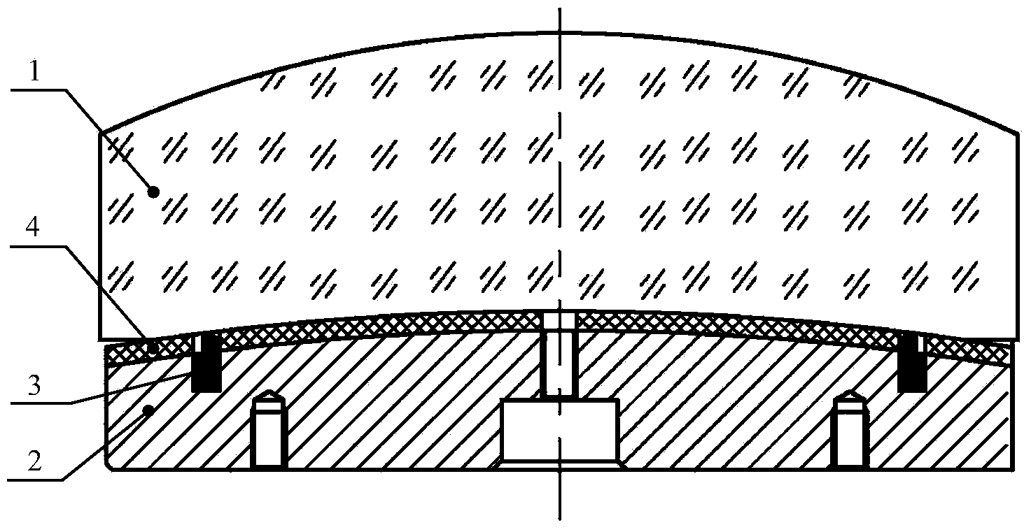
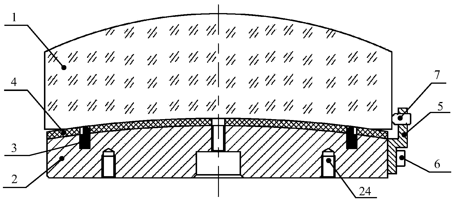
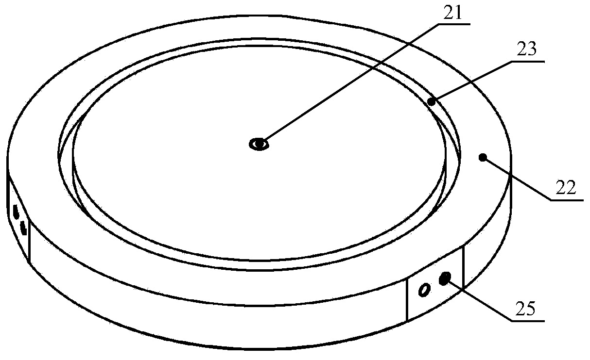
[0020] Such as figure 2 with image 3 As shown, a vacuum fixture for processing and centering an optical element, the fixture includes an optical element 1, a vacuum fixture body 2, a sealing ring 3 and a protective layer 4, and the center of the vacuum fixture body 2 is provided with an air pumping center hole 21 , the upper surface of the vacuum chuck body 2 is provided with a support surface 22, the support surface 22 is provided with an annular groove 23, the sealing ring 3 is arranged in the annular groove 23, the protective layer 4 is arranged on the support surface 22, the optical element 1 Set on the protective layer 4; the fixture also includes an adjustment bracket 5, a screw 6 and a differential nut 7, the adjustment bracket 5 is fixed on the side of the vacuum clamp body 2 through the screw 6, and the differential nut 7 ...


PUM


Abstract

The invention discloses a vacuum clamp for centering an optical element in the machining process and belongs to the field of optical manufacturing. The vacuum clamp solves the problem that due to the fact that a hammer and a dial indicator are used for centering a small and ultra-thin optical element in the traditional milling and polishing processes, edges of the optical element are broken and damaged. The clamp comprises the optical element, a vacuum clamp body, a sealing ring and a protecting layer. The sealing ring and the protecting layer are arranged on the vacuum clamp body. The optical element is arranged on the protecting layer. The clamp further comprises an adjusting support and a differential nut. The adjusting support is fixed on the side face of the vacuum clamp body. The differential nut is fixed to the adjusting support. The optical element is centered through the adjusting support. According to the vacuum clamp for the optical element in the machining process, by means of trace precise adjustment of the differential nut, and the small and ultra-thin optical elements can be centered safely and fast in the machining process.

Description

technical field [0001] The invention belongs to the field of optical manufacturing, and in particular relates to a vacuum fixture for processing and centering optical elements. Background technique [0002] As optical instruments are increasingly used in aerospace applications, the demand for ultra-light, ultra-thin optical components is also increasing. Optical components need to effectively control the eccentricity of the components during the manufacturing process, which requires a high-precision centering method. In the processing of optical components, optical components often use such as figure 1 The shown vacuum adsorption clamping method needs tools such as a dial indicator and a hammer to manually tap the edge of the mirror for centering. The mirror produces micro-displacement under the instantaneous impact force of the hammer to achieve centering. For large and medium-sized components, this method is more feasible; for small and ultra-thin components, hammering ...

Claims


Application Information

Patent Timeline
Patent Type & Authority Applications(China)
IPC IPC(8): B24B13/005
CPCB24B13/0055
Inventor 彭利荣隋永新杨怀江
Owner CHANGCHUN INST OF OPTICS FINE MECHANICS & PHYSICS CHINESE ACAD OF SCI
Why Eureka
Try Eureka