Engine with variable compression ratio

A compression ratio, engine technology, applied in the direction of machine/engine, mechanical equipment, etc., can solve the problems of reducing compression ratio, high processing difficulty, inconvenient to put into production, etc., to achieve the effect of improving power, convenient control and simple structure

Inactive Publication Date: 2014-11-12
范伟俊
View PDF6 Cites 3 Cited by
  • Summary
  • Abstract
  • Description
  • Claims
  • Application Information

AI Technical Summary

Problems solved by technology

[0002] The compression ratio of traditional engines is generally fixed. In recent years, foreign countries have begun to shift the direction of research to engines with variable compression ratios to meet the different requirements of engines for compression ratios under different operating conditions. When the engines are under medium and low loads, In order to improve the emission level of the engine, it is necessary to use a larger compression ratio, and to use a higher boost pressure at high loads, it is necessary to reduce the compression ratio, which can improve the fuel efficiency and output power of the engine. At present, domestic research has begun to Engines with variable compression ratio, but most of them have complex structures and high processing difficulties, which are not convenient for mass production

Method used


Image

  • Engine with variable compression ratio
  • Engine with variable compression ratio

Examples


Embodiment Construction

[0016] Below in conjunction with accompanying drawing, the present invention will be further described:

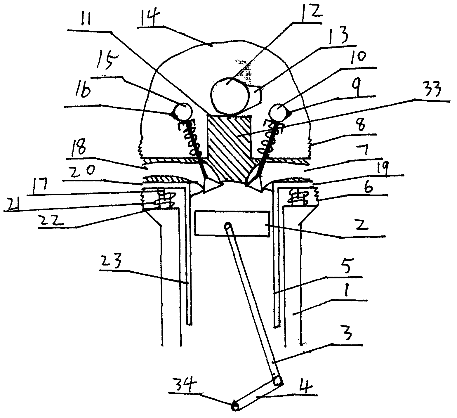
[0017] figure 1 with figure 2 As shown, it is a schematic diagram of the horizontal and vertical cross-sectional structure of the present invention, and the engine can be seen when it is cut open, including a cylinder block 1, a cylinder head 33 and a cylinder head cover 14 arranged on the cylinder head 33, and a cylinder barrel 5 is arranged in the cylinder block 1 , Piston 2, connecting rod 3, crank 4 and crankshaft 34.

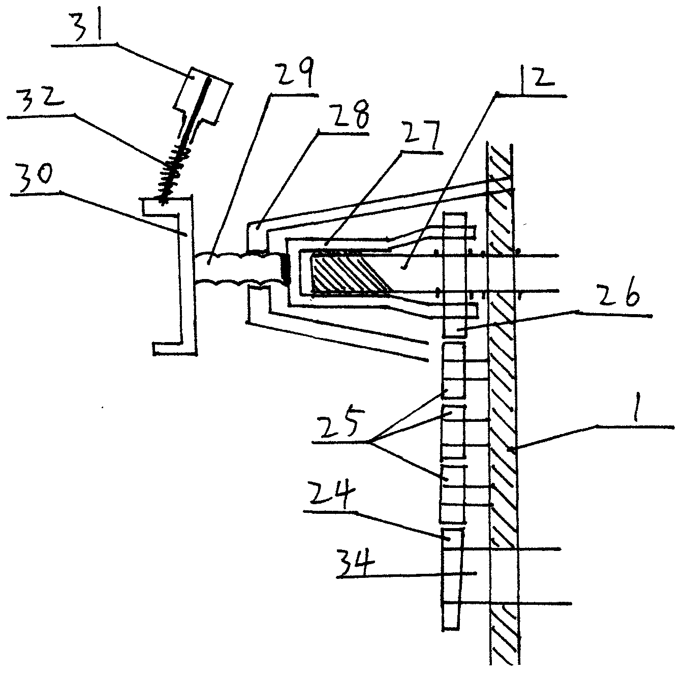
[0018] The center of cylinder head 33 tops is provided with planar bar 11, and the top of planar bar 11 is provided with cam 13, and cam 13 is fixedly connected on the camshaft 12, and one end of camshaft 12 is provided with oblique tooth pattern, has inner cavity The sliding wheel 27 of the tooth pattern sleeve that matches with oblique tooth pattern. The sliding wheel 27 is driven by the crank gear 24 at one end of the crankshaft 34, and the driven...


PUM


Abstract

The invention discloses an energy-saving engine. The engine comprises a cylinder body, a cylinder cover, a cylinder head cover, a cylinder barrel, a crankshaft, a connecting rod and a piston, and is characterized in that a flat bar is arranged at the top end of the cylinder cover; a cam is arranged above the flat bar and fixedly connected onto a cam shaft; oblique insection and a sliding wheel matched with the oblique insection are arranged at one end of the cam shaft; the sliding wheel is driven by a crankshaft gear at one end of the crankshaft through a transmission mechanism, and a relative angle between the cam and the crankshaft can be changed by the transmission mechanism; the upper edge periphery of the cylinder cover and the lower edge periphery of the cylinder head cover are connected through an upper rubber sleeve, and the lower edge periphery of the cylinder cover and the upper edge periphery of the cylinder body are connected through a lower rubber sleeve; and two pins are symmetrically arranged on the left lower surface and the right lower surface of the cylinder cover, sleeves glidingly matched with the pins are arranged on the left upper surface and the right upper surface of the cylinder body, and springs are arranged on the outer sides of the pins and the sleeves in a sleeving manner. According to the energy-saving engine, the compression ratio of the engine can be changed, the structure is simple, the control is facilitated, engine power can be effectively improved, and fuel economy is improved.

Description

technical field [0001] The invention relates to an engine, especially an engine with variable compression ratio. Background technique [0002] The compression ratio of traditional engines is generally fixed. In recent years, foreign countries have begun to shift the direction of research to engines with variable compression ratios to meet the different requirements of engines for compression ratios under different operating conditions. When the engines are under medium and low loads, In order to improve the emission level of the engine, it is necessary to use a larger compression ratio, and to use a higher boost pressure at high loads, it is necessary to reduce the compression ratio, which can improve the fuel efficiency and output power of the engine. At present, domestic research has begun to Engines with variable compression ratio, but most of them have complex structures and high processing difficulties, which are not convenient for mass production. Contents of the inv...

Claims


Application Information

Patent Timeline
Patent Type & Authority Applications(China)
IPC IPC(8): F02B75/04
Inventor 范伟俊
Owner 范伟俊
Why Eureka
Try Eureka