
Heat exchanger for indirect air-cooling system of millions of units of power station

A technology of one million units and an air cooling system, applied in heat exchange equipment, lighting and heating equipment, tubular elements, etc., can solve the problems of increasing the air side resistance, increasing the height of the intercooling tower, and the size of the intercooling tower, etc. Heat transfer effect, overall resistance increase, good heat transfer effect

Active Publication Date: 2014-11-12
BEIJING SHOUHANG IHW RESOURCES SAVING TECH CO LTD
View PDF4 Cites 3 Cited by
  • Summary
  • Abstract
  • Description
  • Claims
  • Application Information

AI Technical Summary

Problems solved by technology

[0006] 3) The density of aluminum is low, only 34.5% of steel
[0010] The indirect air-cooling system of one million units requires a large heat exchange area, and the number of four-tube double-flow heat exchangers is large, which will make the size of the intercooling tower too large and increase the initial investment
In response to this problem, if the area corresponding to the two rows of tubes is increased according to the original fin form of four rows of tubes and double flow, although the heat transfer coefficient is high, it will greatly increase the resistance of the air side, and the height of the intercooling tower will be forced to increase

Method used


Image

  • Heat exchanger for indirect air-cooling system of millions of units of power station
  • Heat exchanger for indirect air-cooling system of millions of units of power station
  • Heat exchanger for indirect air-cooling system of millions of units of power station

Examples


Embodiment 1

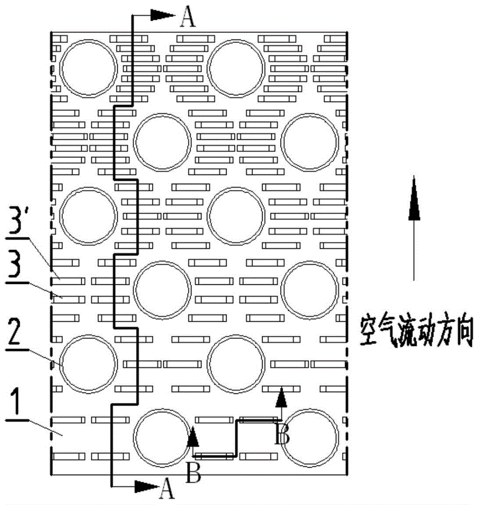
[0038] see figure 1 , figure 2In this embodiment, the first row of piercing holes corresponds to 2 groups of bridge-shaped protrusions, the second row of piercing holes corresponds to 3 groups of bridge-shaped protrusions, and so on, and the sixth row of piercing holes corresponds to 7 groups of bridge-shaped protrusions. Under the guidance of both sides of each bridge piece, the airflow flows through the heat exchange fins in a predetermined direction without being strongly blocked, so the wind resistance will not increase significantly. The distance between the bridge-shaped protrusions corresponding to the first row of piercing holes is 10 mm; as the airflow direction decreases, the distance between the bridge-shaped protrusions corresponding to the sixth row of piercing holes is 1.2 mm.

Embodiment 2

[0040] Such as Figure 4 As shown, in this embodiment, the first row of piercing holes corresponds to 2 sets of bridge-shaped protrusions, the second row of piercing holes corresponds to 4 sets of bridge-shaped protrusions, and so on, and the sixth row of piercing holes corresponds to 12 sets of bridge-shaped protrusions . In this embodiment, the number of bridge-shaped protrusions is an even number, and the effect is that the airflow flows through the heat exchange fins in a predetermined direction under the guidance of both sides of each bridge piece, without being strongly blocked, so the wind resistance will not increase significantly.

Embodiment 3

[0042] Such as Figure 5 As shown, in this embodiment, the first row of piercing holes corresponds to 1 set of bridge openings, the second row of piercing holes corresponds to 3 sets of bridge openings, and so on, the sixth row of piercing holes corresponds to 11 sets of bridge openings. In this embodiment, the number of bridge-shaped protrusions is an odd number, and the effect is the same as above. Under the guidance of both sides of each bridge piece, the airflow flows through the heat exchange fins in a predetermined direction without being strongly blocked, so the wind resistance will not increase significantly.


PUM


Abstract

The invention provides a heat exchanger for an indirect air-cooling system of millions of units of a power station. A heat sink comprises a cooling base body and cooling fins, wherein the cooling fins are arranged on the cooling base body. The heat exchanger is characterized in that multiple rows of parallel heat exchange base tube penetrating installation holes are formed in the cooling fins, a bridge-shaped protrusion is arranged between every two adjacent heat exchange base tube penetrating installation holes in each row, and the two ends of each bridge-shaped protrusion are connected with a fin body of the corresponding cooling fin so that a face which forms an angle smaller than or equal to 90 degrees together with the fin body can be formed. The heat exchanger has the advantages that all parts of the heat sink can exchange heat in a balanced mode, and overall heat exchange performance can be effectively enhanced without largely increasing overall resistance of the fins.

Description

Technical field: [0001] The invention relates to a heat exchanger used in an indirect air-cooling system of one million units of a power station. The product is used in the air-cooling systems of thermal power plants, nuclear power plants and the like to complete heat exchange. The specific form is that the fins used are multi-row tube fins in the form of open bridges. The number of open bridges gradually increases, and the heights of the open bridges are different. Background technique [0002] my country's economy has continued to develop at a high speed in recent years, and the power supply has become increasingly tense. Therefore, it is imperative for the power industry to accelerate the development of large-capacity steam turbines. The production of electric power industry not only consumes a large amount of primary energy, but also consumes a large amount of water resources. However, my country is a country lacking in water resources and extremely unevenly distributed...

Claims


Application Information

Patent Timeline
Patent Type & Authority Applications(China)
IPC IPC(8): F28F1/32
Inventor 黄文佳黄文博李会利王帅
Owner BEIJING SHOUHANG IHW RESOURCES SAVING TECH CO LTD
Learn More