
A spark plug

A spark plug and nickel layer technology, applied in the field of spark plugs, can solve the problems of easy thinning of the nickel layer, low electric field strength, and reduced peeling resistance of the nickel layer

Active Publication Date: 2014-11-12
NGK SPARK PLUG CO LTD
View PDF8 Cites 10 Cited by
  • Summary
  • Abstract
  • Description
  • Claims
  • Application Information

AI Technical Summary

Problems solved by technology

[0010] However, when the terminal electrode is provided with a concave portion as described above, the thickness of the nickel layer tends to become non-uniform, which easily leads to a decrease in corrosion resistance and peeling off of the nickel layer.
Specifically, since the electric field intensity is relatively low on the bottom surface of the concave portion, the nickel layer tends to become thinner, and there is a possibility that the corrosion resistance is insufficient.
On the other hand, for the portion of the terminal electrode located on the outer periphery of the concave portion, since the electric field intensity becomes relatively high, the nickel layer tends to become thicker, and the difference in thermal expansion between the nickel layer and the terminal electrode becomes larger (in other words, In other words, the thermal stress applied to the nickel layer becomes larger), and there is a risk that the peeling resistance of the nickel layer will decrease

Method used


Image

  • A spark plug
  • A spark plug
  • A spark plug

Examples


Embodiment Construction

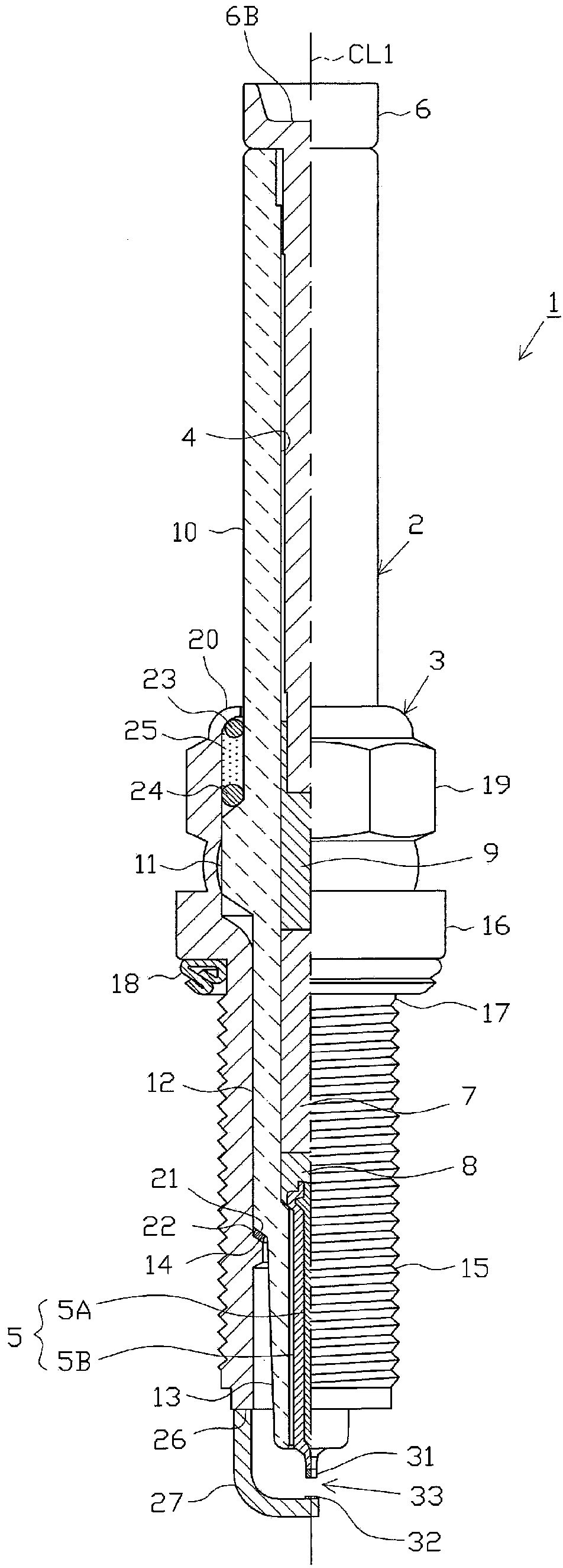
[0042] Hereinafter, an embodiment will be described with reference to the drawings. figure 1 It is a partially cutaway front view showing the spark plug 1 . In addition, in figure 1 In the description, the direction of the axis line CL1 of the spark plug 1 is defined as the vertical direction in the drawing, the lower side is defined as the front end side of the spark plug 1 , and the upper side is defined as the rear end side.

[0043] The spark plug 1 is composed of a cylindrical insulator 2 as an insulator, a cylindrical main body metal case 3 holding the insulator 2, and the like.

[0044] The insulator 2 is formed by sintering alumina or the like as known, and includes in its outer shape: a rear end side body portion 10 formed on the rear end side; a large diameter portion 11 larger than the rear end side body portion. 10 is formed protruding outward in the radial direction at a position closer to the tip side; an intermediate body portion 12 is formed at a position clo...


PUM

PropertyMeasurementUnit
Thicknessaaaaaaaaaa
Average cross-sectional areaaaaaaaaaaa
Thicknessaaaaaaaaaa

Abstract

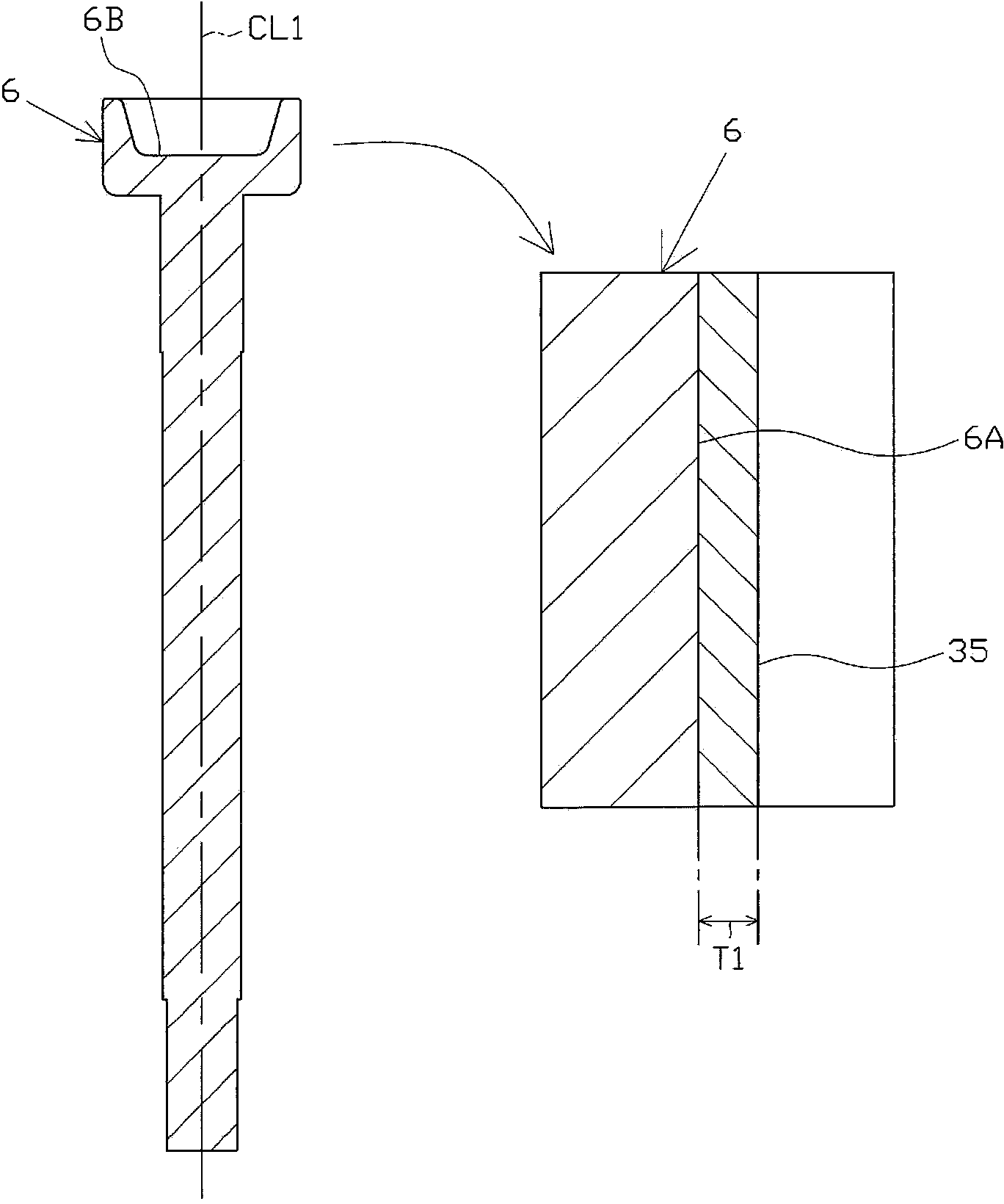
A spark plug is provided. A recess part is disposed at the rear end of a terminal electrode and a nickel layer is formed at the rear end of the terminal electrode. In the spark plug, the corrosion resistance of the terminal electrode is fully enhanced and inhibition for peeling of the nickel layer is more reliable. The spark plug (1) comprises: an insulation electrotechnical porcelain (2) provided with an axis hole (4) penetrating along the axis direction (CL1); and the terminal electrode (6), wherein the rear end of the terminal electrode is inserted into the axis hole (4) in a state that the rear end of the terminal electrode protrudes out from the rear end of the insulation electrotechnical porcelain (2). The rear end of the terminal electrode (6) is provided with the recess part adopting the axis direction (CL1) as the depth direction. The nickel layer (35) is disposed on the external surface of the rear end of the terminal electrode (6), and has a thickness of 3-25 [mu]m. In a cross section orthogonal to the external surface of the nickel layer (35), the average section area of crystal grains forming the nickel layer (35) is 50-500 [mu]m<2>.

Description

technical field [0001] The present invention relates to a spark plug used in internal combustion engines and the like. Background technique [0002] The spark plug is attached to an internal combustion engine (engine), etc., and is used to ignite the air-fuel mixture in the combustion chamber. In general, a spark plug includes: an insulator having a shaft hole extending in an axial direction; a center electrode inserted into a top end side of the shaft hole; a terminal electrode inserted into a rear end side of the shaft hole; a main body metal case , which is arranged on the outer periphery of the insulator; and a ground electrode, which is fixed on the top end of the metal shell of the main body. In addition, the rear end portion of the terminal electrode itself is exposed from the rear end of the insulator, and a terminal for power supply is connected to the rear end portion. In addition, the rear end of the insulator itself is exposed from the rear end of the main meta...

Claims


Application Information

Patent Timeline
IPC IPC(8): H01T13/20H01T21/02
CPCH01T13/04
Inventor 杉田真那须弘哲
Owner NGK SPARK PLUG CO LTD
Learn More