BBU wire distribution cavity

A wiring and cable technology, applied in the field of BBU wiring cavity, can solve problems such as cable damage, and achieve the effect of reducing the probability of pulling and damage

Active Publication Date: 2014-11-12
LINYI YIQUN PACKAGING PROD CO LTD
View PDF5 Cites 4 Cited by
  • Summary
  • Abstract
  • Description
  • Claims
  • Application Information

AI Technical Summary

Problems solved by technology

[0006] The embodiment of the present invention provides a BBU wiring cavity, which solves the problem that other cables that do not need to be repaired or replaced are easily caused during the process of pulling the cable out of the through hole when repairing or replacing the damaged cable. The problem of being damaged by pulling

Method used


Image

  • BBU wire distribution cavity
  • BBU wire distribution cavity
  • BBU wire distribution cavity

Examples


Embodiment 1

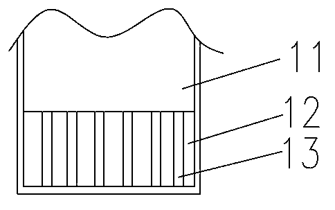
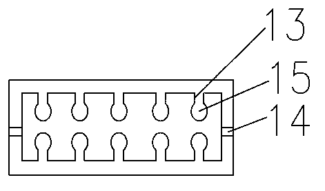
[0046] This embodiment provides a BBU wiring cavity, such as Figure 1a and Figure 1bAs shown, it includes a cavity body 11 and a cable waterproof module 12. The cavity body 11 is provided with a cable interface and a fixing unit 14 for fixing the cable waterproof module 12; the cable waterproof module 12 is provided with a The through hole 15 of the cable; each through hole 15 is provided with a notch 13 in the direction of cable routing, the notch 13 runs through the cable waterproof module 12, and the width of the notch 13 is smaller than the cable passing through the through hole diameter, so that the cable is pressed into the through hole 15 through the notch 13.

[0047] The cables include electric cables and optical cables, and the cavity body 12 is provided with a cable interface for passing the electric cables and optical cables. The fixing unit 14 can fix the position of the cable waterproof module 12 so that the cable waterproof module 12 does not become loose or ...

Embodiment 2

[0050] This embodiment also provides a BBU wiring cavity, such as Figure 2a As shown, it includes a cavity body 21 and a cable waterproof module 22. The cavity body 21 is provided with a cable interface and a fixing unit 23 for fixing the cable waterproof module; the cable waterproof module 22 is provided with a The through hole 24 of the cable; each through hole 24 is provided with a notch 25 in the direction of cable routing, the notch runs through the cable waterproof module, and the width of the notch 25 is smaller than the diameter of the cable passing through the through hole 24 , for pressing the cable into the through hole through the notch 25 .

[0051] In the BBU wiring compartment provided in this embodiment, see Figure 2a , the above-mentioned cable waterproof module 22 can be divided into several detachably connected subunits 221 , and each subunit 221 includes a through hole 24 . In this way, when the cable on a certain subunit 221 needs to be repaired or rep...

Embodiment 3

[0063] This embodiment also provides a BBU wiring cavity, such as image 3 As shown, it includes a cavity body 31 and a cable waterproof module 32. The cavity body 31 is provided with a cable interface and a fixing unit 311 for fixing the cable waterproof module 32; the cable waterproof module 32 is provided with a The through hole 321 of the cable; each through hole 321 is provided with a notch 3211 in the direction of cable routing, the notch 3211 runs through the cable waterproof module 32, and the width of the notch 3211 is smaller than the line that passes through the through hole 321 The diameter of the cable is used to press the cable into the through hole 321 through the notch 3211 .

[0064] In the BBU wiring cavity provided in this embodiment, the cable waterproof module 32 can be divided into several detachably connected subunits 322 , and each subunit 322 includes a through hole 321 . In this way, when the cable on a certain subunit 322 needs to be repaired or rep...


PUM


Abstract

The invention discloses a BBU wire distribution cavity and relates to the technical field of mobile communications. The BBU wire distribution cavity solves the problem that when a damaged cable is maintained or replaced, other cables not needing to be maintained or replaced are prone to being pulled and damaged in the process of drawing the damaged cable out of a through hole. The BBU wire distribution cavity comprises a cavity body and a waterproof cable module, a cable interface and a fixing unit are arranged in the cavity body, the fixing unit is used for fixing the waterproof cable module, the waterproof cable protective module is provided with through holes for cables, each through hole is provided with a notch in the cable routing direction, the notches penetrate through the waterproof cable module, and the width of each notch is smaller than the diameter of the cable penetrating through the corresponding through hole, so that the cables are pressed into the through holes through the notches. The BBU wire distribution cavity is applicable to BBU equipment.

Description

technical field [0001] The invention relates to the technical field of mobile communication, in particular to a BBU wiring cavity. Background technique [0002] A base station is a form of a radio station, which refers to a radio transceiver station that transmits information between a mobile communication switching center and a mobile phone terminal in a certain radio coverage area. With the development of base station construction, distributed base stations have become the most important choice in terms of reducing network construction and maintenance costs and saving site resources. [0003] The distributed base station adopts the radio frequency module remote technology, installs RRU (Radio Remote Unit, radio remote unit) at the antenna end, and connects to the macro base station or independent BBU (Base Band Unit, base band unit) through optical fiber. RRU is a kind of indoor and outdoor integrated equipment, which has the characteristics of large capacity, easy instal...

Claims


Application Information

Patent Timeline
Patent Type & Authority Applications(China)
IPC IPC(8): H02G3/08G02B6/44
Inventor 金庆浩连颖
Owner LINYI YIQUN PACKAGING PROD CO LTD
Why Eureka
Try Eureka