Tissue heating device and RF heating method with tissue attachment feature

a tissue heating device and tissue heating technology, applied in the field of catheters, can solve the problems of limited conventional atherectomy catheters, acute and potentially life-threatening reclosure of the artery, and a limited range of atherectomy catheters

Inactive Publication Date: 2007-02-06
CARDIOVASCULAR TECH INC
View PDF9 Cites 4 Cited by
  • Summary
  • Abstract
  • Description
  • Claims
  • Application Information

AI Technical Summary

Benefits of technology

[0012]To achieve these and other objects, there is provided a device for removing atheromas from a body lumen. The device includes an elongate catheter having a proximal end and a distal end. The catheter has a wall that defines a compartment within the catheter near its distal end, and a window is formed through the catheter wall to allow entry into the compartment. The catheter incorporates an electrically conductive tissue cutting element. A means is provided for generating an electrical current in the cutting element to heat the cutting element and adjacent tissue at least to a selected temperature above normal body temperature (i.e. 37 degrees C.). A carrier is mounted movably relative to the catheter, for supporting the cutting element proximate the window and for a controlled movement of the cutting element along and adjacent the window. The catheter is flexible and maneuverable to locate its distal tip within a body lumen and to place the window against a tissue wall segment of the body lumen to acquire tissue within the compartment. The cutting element, when heated and when undergoing the controlled movement, severs the acquired tissue.
[0015]The preferred cutting element is a flat band, having a thickness of about 0.015 inches and a substantially greater width. The band achieves a highly accurate and fine cut of the tissue, considerably reducing the pulling and tearing of tissue as compared to the conventional oscillating or rotating blades. Unwanted tissue is severed more cleanly, reducing patient risk. Further, it is believed that the elevated temperatures of the band and adjacent tissue have a sealing or cauterizing effect along the region of the cut. This is believed to result in a substantial reduction in restonosis in the treated artery.
[0017]The carrier preferably includes a cartridge contained within the compartment. The cartridge can have an axialy extended cartridge wall, a cartridge opening and a cutting edge along the cartridge opening for supporting the cutting element. A control means is coupled to the cartridge proximal end, and operable to selectively position and move the cartridge within the compartment, to provide the controlled movement of the cutting element. Preferably the cartridge wall is longer axially than the window, so that the cartridge can be positioned to substantially close the window and thus capture severed tissue. With tissue secured in this manner, there is no need for a suction device or other means to withdraw tissue proximally through the catheter immediately after it is cut. With no need to pay attention to a vacuum or suction means, the physician is able to direct more attention to the atherectomy procedure at hand.
[0026]Thus in accordance with the present invention, there is provided an atherectomy device and procedure suitable for treating soft occlusions and calcified occlusions alike, with clean and accurate cutting that reduces the risk of tissue tearing and escaping into the blood vessel under treatment. The catheter is versatile, due to its flexibility for traversing tortuous vessels and for the ability to cut in either an arcuate or axial path. The application of heat is concentrated along the region of the cut, i.e. the cutting element and adjacent tissue, reducing the required cutting force, increasing cutting accuracy and tending to cauterize or seal the region of the cut, thus tending to substantially prevent restonosis.

Problems solved by technology

When encountering softer occlusions, however, the device presents the risk of an occlusion breaking off during the atherectomy procedure, causing an acute and potentially life-threatening reclosure of the artery.
The abrasive tip may inadvertently remove endothelium cells during catheter insertion, use or removal, thereby creating sites for potential lesions.
Conventional atherectomy catheters are limited principally to an axial cutting direction and subject to smooth cell muscle migration (restonosis) after treatment.

Method used


Image

  • Tissue heating device and RF heating method with tissue attachment feature
  • Tissue heating device and RF heating method with tissue attachment feature
  • Tissue heating device and RF heating method with tissue attachment feature

Examples


Embodiment Construction

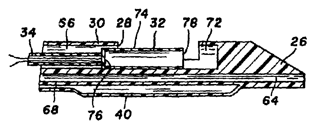
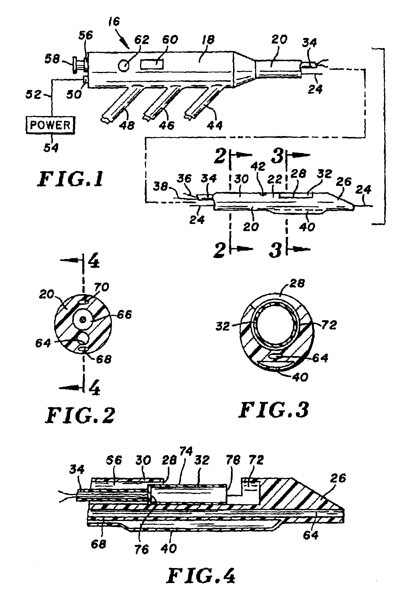
[0040]Turning now to the drawings, there is shown in FIG. 1 an atherectomy device 16 for removing unwanted tissue from body lumens, more particularly blood vessels. The device includes a control housing or handle 18, and an elongate and pliable catheter 20 connected at its proximal end to the handle.

[0041]Catheter 20 is formed of a biocompatible polymer such as Pebax (brand name) polyether block amides, Pellethane (brand name) polyurethane or polyimide, and can have an outside diameter in the range of 3 Fr. (1 mm) to 8 Fr. (2.7 mm) or larger. Catheter 20 includes several lumens that run axially from handle 18 to a distal end region 22. A guidewire 24, contained within one of the lumens, extends proximally beyond handle 18 and distally beyond a tapered distal tip 26 of the catheter. Further lumens are provided in the catheter, for delivery of contrast fluid or treatment fluid to the distal end region, and for balloon inflation. While not shown, a braided or other filament structure c...


PUM


Abstract

A tissue cutting device includes a catheter with a window at its distal tip for admitting tissue into a catheter compartment. A cylindrical cartridge in the compartment has a cutting edge that supports an electrically conductive cutting element, e.g. a band or wire. The cutting element and adjacent tissue can be heated to a selected temperature by generating an electrical current through the cutting element. The catheter is maneuverable to position its distal end near the tissue to be cut. The catheter incorporates a dilatation balloon or other feature to urge the catheter against the tissue, so that at least part of the tissue may enter the compartment through the window. Then, the cartridge is manipulated from the catheter's proximal end to move the cutting edge across the window, cutting the tissue. According to alternative embodiments, the cartridge is either rotated or moved axially relative to the catheter and, in either event may be capable of closing the catheter window when the cut is complete. Further alternatives involve either placing an indifferent electrode on the patient and providing an RF signal via a single conductor to the cutting element for ohmic heating, or providing an RF (or a DC) current through the cutting element and two separate conductors for direct resistive heating of the cutting element.

Description

CROSS REFERENCE TO RELATED APPLICATIONS[0001]This application is a continuation of Ser. No. 10 / 404,720 filed on Apr. 1, 2003, now U.S. Pat. No. 6,872,204 Patterson et al., which is a Division of Ser. No. 09 / 804,009 filed Mar. 12, 2001 and issued on Apr. 1, 2003 as U.S. Pat. No. 6,540,761; Division of Ser. No. 09 / 256,020, filed Feb. 23, 1999, U.S. Pat. No. 6,214,024; Division of Ser. No. 08 / 899,490 filed on Jul. 19, 1997, U.S. Pat. No. 5,876,369, and a Division of application Ser. No. 08 / 376,226 filed on Jan. 23, 1995, U.S. Pat. No. 5,665,062.BACKGROUND OF THE INVENTION[0002]The present invention relates to devices for removing obstructions from body lumens, and more particularly to catheters for removing atherosclerotic plaque and thrombotic occlusions from blood vessels.[0003]Atherectomy catheters are known for their utility in removing atherosclerotic plaque and thrombotic occlusions from arteries. While intended mainly for use in the coronary arteries, such catheters may as well ...

Claims


Application Information

Patent Timeline
Patent Type & Authority Patents(United States)
IPC IPC(8): A61B18/04A61B18/18A61B18/14
CPCA61B18/1492A61B2218/007A61B2018/1861A61B2018/00601
Inventor HOUSER, RUSSELL A.
Owner CARDIOVASCULAR TECH INC
Why Eureka
Try Eureka