Device for preventing current limiting circuit from being adjusted excessively

A technology of current limiting circuit and circuit module, applied in circuit devices, emergency protection circuit devices, emergency protection circuit devices for limiting overcurrent/overvoltage, etc. and other issues to achieve good protection

Active Publication Date: 2014-11-12
SG MICRO
View PDF6 Cites 9 Cited by
  • Summary
  • Abstract
  • Description
  • Claims
  • Application Information

AI Technical Summary

Problems solved by technology

This situation where the output current becomes zero for a short time will bring risks to the upstream power supply, such as the peripheral inductance and capacitance of the upstream power supply, thus generating a current or voltage spike and destroying the chip

Method used


Image

  • Device for preventing current limiting circuit from being adjusted excessively
  • Device for preventing current limiting circuit from being adjusted excessively
  • Device for preventing current limiting circuit from being adjusted excessively

Examples


Embodiment Construction

[0027] Below with the accompanying drawings ( Figure 2-Figure 8 ) to illustrate the present invention.

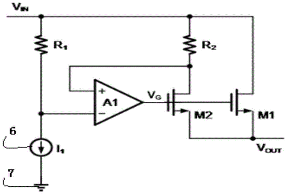
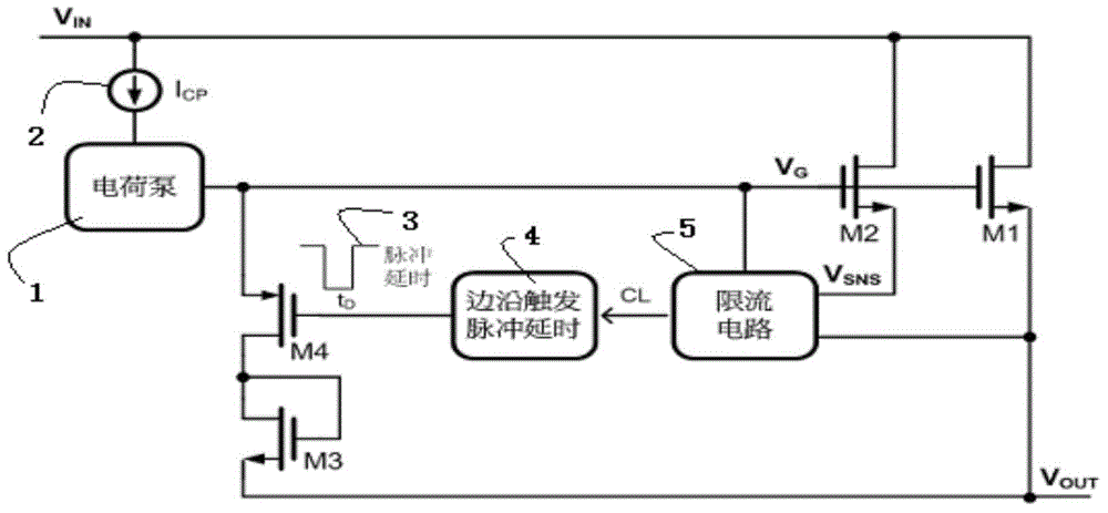
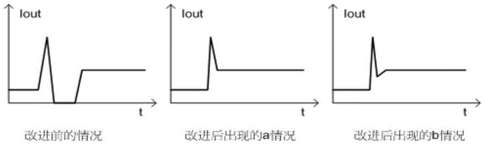
[0028] figure 2 It is a schematic diagram of the device implementing the present invention to prevent excessive adjustment of the current limiting circuit, wherein the power MOS transistor M1 and the induction MOS transistor M2 are both NMOS transistors. image 3 It is a comparative schematic diagram of the output current Iout~t time curves of the prior art device and the device of the present invention in the current limiting state. Figure 4 yes image 3 Schematic diagram of the equivalent circuit of the current limit adjustment of M4 in the conduction phase. Figure 5 It is a schematic diagram of the device implementing the present invention to prevent excessive adjustment of the current limiting circuit, wherein the power MOS transistor M11 and the induction MOS transistor M21 are both PMOS transistors. Image 6 yes Figure 5 Schematic diagram of the equivalent cir...


PUM


Abstract

The invention provides a device for preventing a current limiting circuit from being adjusted excessively. The device can well protect the safety of an upstream power source by preventing output current from being zero in short time during current limitation. The device comprises a double-MOS-tube structure formed by combining a power MOS tube and an induction MOS tube. A grid of the power MOS tube and a grid of the induction MOS tube are connected. The current output end of the power MOS tube is connected with the voltage output end. The source drain current input end of the power MOS tube and the source drain current input end of the induction MOS tube are connected with the voltage input end. The source drain current output end of the induction MOS tube is connected with a current limiting circuit module. The source drain current output end of the power MOS tube is directly connected with the voltage output end. The current limiting circuit module is connected with the voltage output end, a grid voltage node and an edge trigger pulse delay circuit module. The current limiting circuit module and the edge trigger pulse delay circuit module are connected with the grid voltage node through a selection conducting MOS tube. The selection conducting MOS tube is connected with the voltage output end or the voltage input end through a transition MOS tube.

Description

technical field [0001] The invention relates to current limiting circuit technology, in particular to a device for preventing excessive adjustment of the current limiting circuit. The device prevents the output current from being zero for a short time during current limiting to better protect the safety of the upstream power supply. The over-adjustment refers to the moment when the chip output current is zero in the adjustment of the output current of the chip by the current-limiting circuit when the load switch chip with the current-limiting circuit suddenly changes to the current-limiting state in the normal working state, for example, several microseconds to several During the period of one hundred microseconds, the output current of the chip is zero. Background technique [0002] When the output port encounters hot plugging, the equivalent resistance of the downstream load suddenly decreases or the ground is suddenly shorted, the chip (especially the high-current switchi...

Claims


Application Information

Patent Timeline
Patent Type & Authority Applications(China)
IPC IPC(8): H02H9/02
Inventor 郑辰光
Owner SG MICRO
Why Eureka
Try Eureka